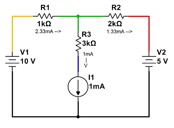
One useful tool when performing circuit analysis is superposition. By considering voltage and current sources one at a time (setting all others equal to zero volts or zero current), voltages and currents in an electrical network containing any number of sources can be analyzed.
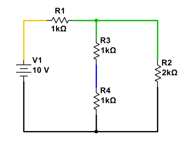
In a simple circuit, DC analysis is straightforward. Resistances in series, parallel, or simple combinations of the two can be numerically lumped together, and the resulting currents and voltages calculated using Ohm’s Law. In the circuit below, for example, the two central 1k resistors can be viewed as a single 2k resistance. This, in parallel with R2, forms 1k of resistance. When R1 is added, the total circuit resistance is 2k. By Ohm’s Law, 5mA of current flow through the circuit. It is fairly straightforward to see that all 5mA flow through R1, and that 2.5mA flow through R2, R3, and R4.
When more than one voltage and/or current source is involved, though, things get trickier. Resistances cannot be simply combined as before, since there could be voltages and/or currents due to several different sources. Another approach is needed.
Fortunately, superposition provides a straightforward, practical way to analyze circuits with multiple power sources. By following a few simple steps, voltages and currents can be calculated through a circuit of arbitrary complexity. (For some configurations, simplification using Wye-Delta conversions may also be needed.)
To analyze current flow in a circuit with multiple sources, analyze the circuit with only one source at a time present, setting all other sources temporarily to zero:
- Replace all voltage sources not being analyzed with a short (zero voltage), and
- Replace all current sources not being analyzed with an open (zero current).
Once these substitutions have been made, re-analyze the circuit, noting the current flow in each branch due to this source. Do the same for any remaining sources, re-enabling them in the circuit, and setting the already-analyzed source to zero voltage or zero current, as appropriate.
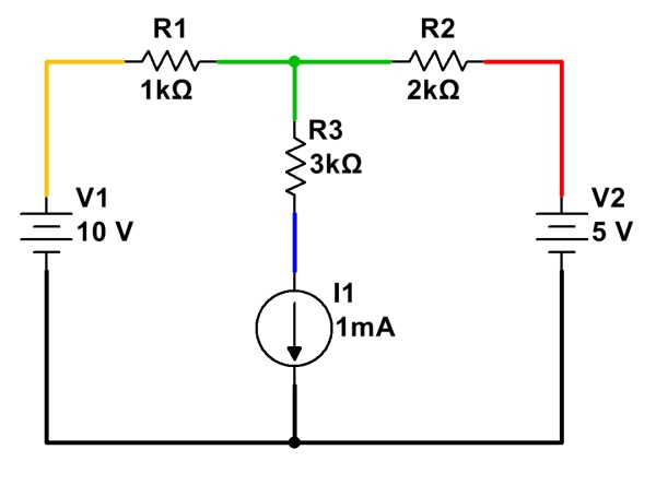
Here is a simple example of circuit analysis of using the above example, with two voltage sources and a current source:
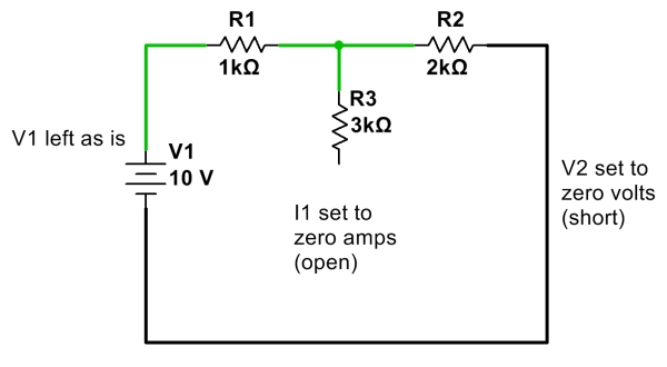
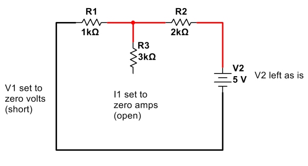
First, calculate and note all currents due to V1 with other sources V2 and I1 removed. (Click for larger.)
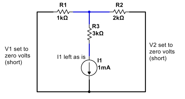
After calculating and noting current flows due to all of the sources, add them up. One way to do this is to assign a color for each source, and note the current flow due to that source through each resistor. (Remember to note which direction each current component flows; current flows going in the same direction add, but currents flowing in opposite directions cancel!)
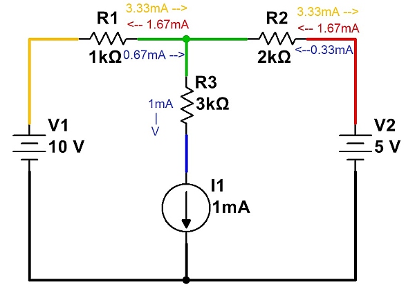
Currents from each source are noted independently. These are then added to determine total current. (Click for larger.)
Once all of the currents have been noted, they can be added (and subtracted, depending on direction) to show the total current flow…
Note that Kirchoff’s Current Law (net current flow into or out of a point is zero) must be satisfied for each point in the circuit. For example, at the node represented in green, 2.33mA of current is flowing in through R1. This current must leave the node, and therefore 1mA flows through R3 and 1.33mA flows through R2. The net current into the node is therefore zero, so no charge accumulates over time.

