
Do you speak Servo?
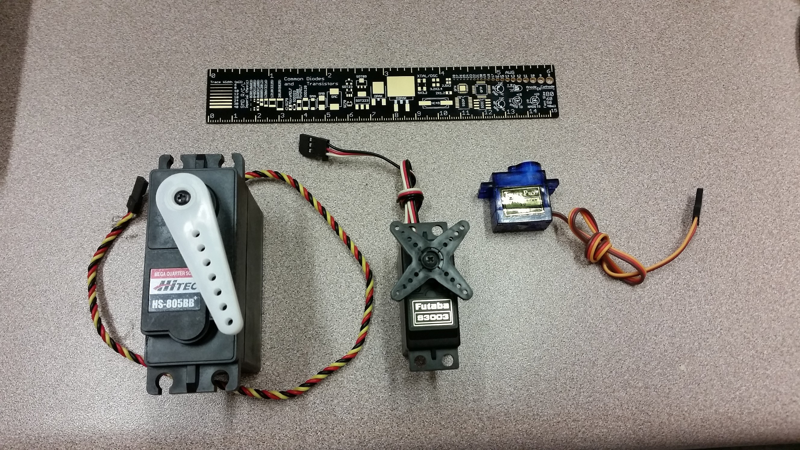
Various standard servo motors (about 180 degrees movement each). Click for larger.
Servo motors (both positional and continuous-rotation) are useful devices. Provide power, ground, and a relatively simple control signal, and the servo’s onboard circuitry handles all of the motor-control tasks, including a closed-loop feedback system to ensure the servo maintains the correct position or speed.
One nice thing about servo motors is that they are easily controlled by a microcontroller with no additional control or current amplification circuitry needed. Constant DC power (typically, 5V-6V) is applied to the servo, and a control signal is provided to the (high-impedance) control line. One microcontroller, depending on application specifics and processor speed, can control as many as a couple dozen servos.
In addition to traditional servos and continuous-rotation servos, small, efficient, and powerful DC brushless “outrunner” motors have recently become popular in many applications such as electric RC aircraft and quadrotor flying drones. Outrunner motors are essentially three-phase AC motors, driven by a custom controller. Conveniently enough, these controllers usually use the standard servo protocol, as well.
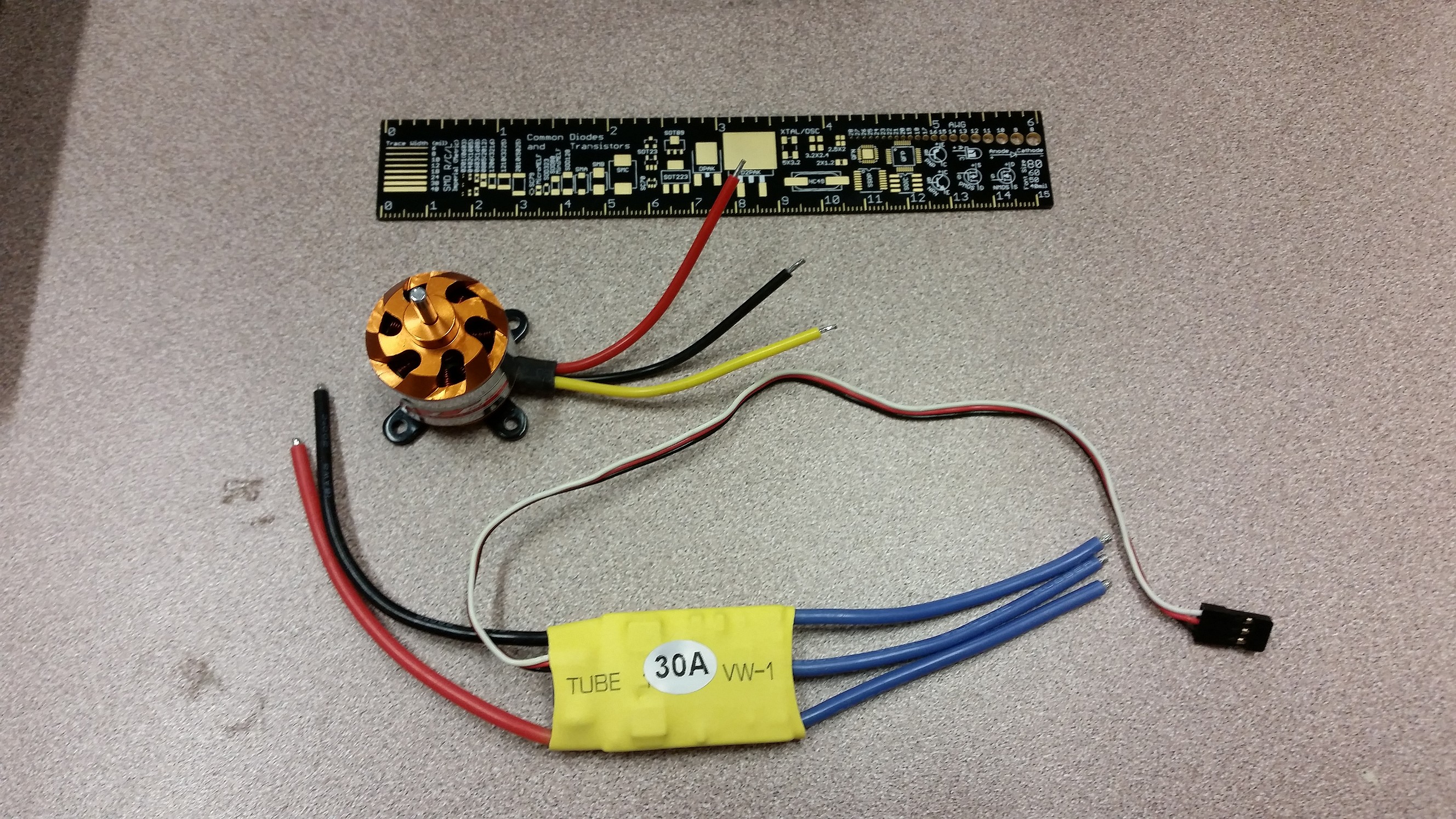
A brushless DC motor and its electronic controller. The controller receives control commands as if it were a servo motor, allowing existing servo motor microcontroller libraries to be easily adapted to control these motors. (Click for larger.)
In a nutshell, servos and similar devices are controlled by the following signal type:
- 5V TTL (5VDC high, 0VDC low);
- High impedance input, easily driven directly by logic;
- 20ms (50Hz) period pulsed input;
- ~0.5ms — ~2.0ms pulse width (varying the pulse width provides the control variable.)
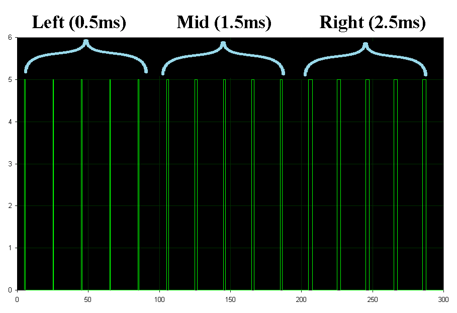
Pulses to control a servo. Five 0.5ms pulses command full movement in one direction; five 1.5ms pulses command movement to the center; and five 2.5ms pulses command movement in the other direction.
One pitfall when working with servos is to think of this signal as a PWM cycle, and calculate servo position based on the duty cycle of the pulse. While technically correct, the “duty cycle” only varies from roughly 1% to 4% when ranging over the entire valid control input range of the servo. A duty cycle of 25%, for example, does not correspond to 25% power, as it would for a motor driven directly by a PWM signal. Rather, a 25% duty cycle pulse train would probably not be understood by the servo controller as a valid signal at all. It’s best to think in terms of pulse width, since changes in pulse width (within a small range) correspond to changes in servo behavior. Even the long 2.5ms pulses are still only 12.5% “duty cycle.”
