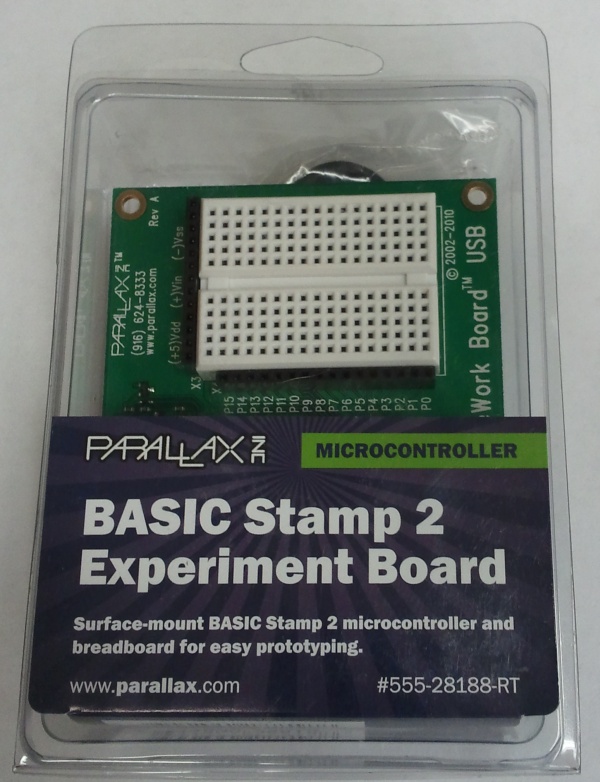
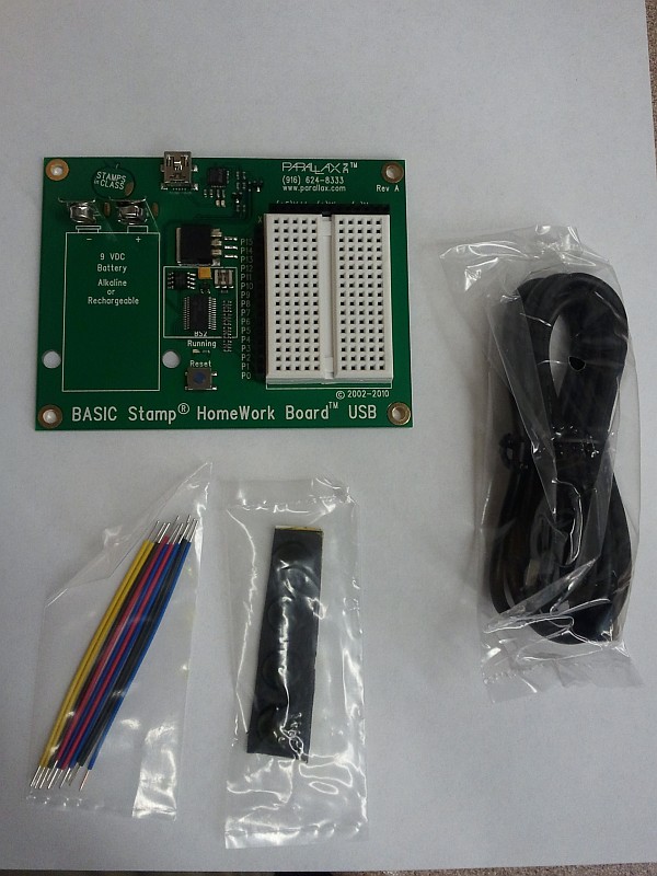
While browsing through a local Radio Shack the other day, I noticed some BASIC Stamp boards in stock. Since new dev boards are always interesting — and since I’ve been programming in BASIC since the days of the dinosaurs early ’80s, I decided it was time I tried one. I certainly like microcontrollers, and for better or worse, BASIC is still my “native” programming language. A BASIC Stamp board is therefore a no-brainer, right?
Well, yes and no…
Setup:
Physical setup of the board is pretty straightforward. To save on cost and packaging, no software is included; you download it from Parallax’s site. Bonus points for environmental responsibility: check.
Unfortunately, Parallax’s site doesn’t have a very intuitive process for locating the board drivers. The directions on the package steer you to www.parallax.com/rt (which I won’t link to and add to the confusion), but that page just offers vaguely-helpful instructions on how to find your product number and type it in. Doing so lets you locate the product page for the specific board you have. Hunting around on that page turns up a link to Parallax’s common software download page for most or all of their BASIC stamp boards (begging the question, why did I have to enter in the product number??)
Once you locate the BASIC Stamp software download page, things fortunately get a lot easier. The page has an easy, obvious “1-2-3” chart front and center. Nice! Click on the first link, install the software, and connect up the board. Simple.
Download the software? Check.
Run the installer? Check.
Plug in the device? Check. (The USB drivers loaded nicely on Windows 7/64bit.)
Launch the software? Check.
Run examples? Uh oh. Unlike the easy “Examples” menu in the Arduino IDE, Parallax’s Basic Stamp Editor software starts up with its default directory in C:\Windows. This is not only useless (that’s not where the examples are or where your programs ought to go) — but potentially dangerous if people start digging around in the Windows directory structure. These boards are marketed to primary and secondary-school students, and this is asking for trouble.
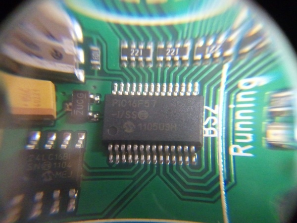
Guessing that the correct location was in the “Program Files (x86)\Parallax” directory (it was), I soon was in more or less the right place. The next challenge was to determine which version of BASIC stamp the board had. This, again, wasn’t specified. A quick check of the packaging turned up a reference to a “BASIC Stamp 2 chip,” so I went with that. (The actual chip turns out to be a garden-variety PIC, presumably with special firmware.)
I fired up a random example from the “BS2” folder — a “connection test” program. It ran, but reported no boards found (even though the board’s lights blinked when programming it.) I tried a few more examples with the same result — no board found.
At that point, I decided to try applying 9V to the battery terminals, theorizing that the board didn’t get its power from USB (like the Arduino boards do.) This worked, and the board was soon running the connection-test example correctly.
Programming
I loaded up another example — “HIGH_LOW.BS2” — and ran it. A LED that I had connected between P0 and Ground blinked dutifully at 1Hz. Success. I modified the delay times to 100ms instead of the default 500ms, and the LED was soon blinking at 5Hz. So far, so good.
Performance
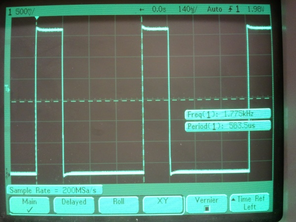
I decided to see what the board could do with the throttle wide open. I commented out the “pause” lines (the board’s dialect of BASIC uses the usual apostrophe-for-comment convention), and re-ran the program. The LED came on dimly (as expected), and the oscilloscope showed a high-frequency output. Dialing in the ‘scope readout showed an output at roughly 1.775kHz, with a 25% duty cycle.
Writing this code in native PIC assembly would produce the same 25% duty cycle: One instruction would be needed to raise the output; one more would lower it, and a “GOTO” instruction to loop back to the beginning would take two cycles (due to the way the PIC uses a simple two-stage pipeline to execute code.)
A PIC clocked at 8MHz would execute code at two million instructions per second (2 MIPS), counting GOTOs and such as two instructions. If this high/low/repeat code were written in assembly, it would take four instruction cycles to execute, resulting in one cycle every two microseconds, or a frequency of 500kHz. The observed frequency, by comparison, is some two hundred eighty times slower than this theoretical maximum. (…and most PICs, including the 16F57, can run much faster than 8MHz if need be.)
That’s not merely slow — that’s glacial! Even the Arduino executes naive C++ code faster than that. Unless the PIC is being clocked extraordinarily slowly, either it’s running the BASIC code as an interpreter (a bad idea), or the compiler is very inefficient.
This calls for more investigation, but my guess is that performance is not high on the priority list for the BASIC Stamp.


