
One of the most popular standard peripherals for microcontroller projects is the ubiquitous 16×2 text LCD display. These displays are useful for the display of information generated by a device (temperatures, voltages, statuses etc.) In addition, they can make debugging a lot easier, by providing a play-by-play description of what is going on.
![[16x2 LCD display]](https://www.paleotechnologist.net/wp-content/uploads/2014/04/lcd.jpg "These are cheap, useful, and easy to work with...")
A typical 16×2 text LCD display. (Image courtesy of Wikipedia.)
8-bit mode is described here. Most of these displays can also run in 4-bit mode if needed, which can save four GPIO pins.
If you’re using an Arduino, the instructions are slightly different (and also slightly easier): check out the Arduino LiquidCrystal tutorial for directions.
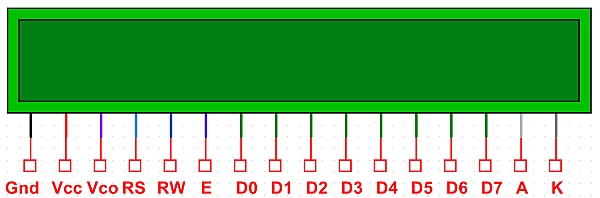
Hardware connection:
A standard parallel 16×2 LCD has a sixteen-pin interface. Numbered from 1 to 16, these typically are:
- Ground
- Vcc (typically 5V, but sometimes 3.3V)
- Contrast
- R/S
- R/W
- E
- D0 through D7
- Backlight anode
- Backlight cathode
Ground and Vcc are connected as you would expect. Contrast is connected to a 10k potentiometer between Ground and Vcc. Connect R/S, R/W, and E to three GPIO pins on your microcontroller. Connect D0 through D7 to the corresponding pins on a single-byte port if using a PIC or similar microcontroller (I typically use PORTD on a PIC16F887). If you’re short one pin, R/W can generally just be grounded instead of being connected to the microcontroller. (Most LCD functions don’t rely on reading data back from the LCD.)
Control and data bytes are sent to the display, one byte at a time, by strobing the E line low. If the R/S line is low, the bytes are interpreted as control codes. If R/S is high, the bytes are interpreted as data to be displayed (in ASCII).
To set up the display, a sequence of control codes should be sent. There are various (minimum) delay requirements after each control code. Here is the sequence to get the display up and running:
- Set R/S low
- Start off with E high
- Send a byte of 0x38:
- Place 0x38 on the data bus (D0 through D7)
- Strobe E low for 1ms (conservative, but works)
- Wait 200ms
- In the same way, send the following bytes in this order:
- 0x0C
- 0x01
- 0x06
- 0x02
- Raise the R/S pin to go into data mode
- Send the data to be displayed as ASCII bytes, one byte at a time.
Here is an LCD driver library, written in assembly for 8-bit PIC microcontrollers. It relies on delay routines from a delay library that I wrote. Both may be freely re-used for noncommercial purposes, as long as attribution information is kept. (CC BY-NC-SA).
