
One of the most important Engineering concepts is that of the closed loop. In order to improve something, you need the ability to change it in appropriate ways — as well as the ability to know whether these changes are making the end result better or worse. Specifically, you need to measure it and determine the amount of error.
The classic example of this is a thermostat. A thermostat connected to a heater might, for example, be set to keep a room at around 20 degrees C. If the room gets significantly warmer than this, no more heat is needed, and the thermostat can shut off the heater. If it gets too cold, heat is needed, and the thermostat turns the heater back on.
This principle is more widely useful than just for home heating controls, however. The same principle, with a few adjustments, can be used for calibration of systems — or measurements.
I recently upgraded the Z axis motion on my 3D printer, which should result in much smoother (and efficient) motion. It’s already resulted in better-looking parts. However, the 8mm lead screws that were suitable had a much different pitch than the threaded rod the old Z-axis design had used. Since 3D printers operate by counting how far they’ve gone, not compensating for this would result in far too much distance between layers. The firmware would rotate the steppers by the same too-large amount, not knowing that the effective mechanical steps-per-mm had been greatly reduced.

The wrong steps-per-mm setting for the Z axis can produce a complete bird’s nest.
Clearly, the 2550 steps/mm Z axis setting had to be reduced. But by how much? As it turns out, since the relationship here is linear, there’s a handy equation you can use to estimate the correct number.
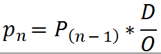
This is, ideally, an iterative process. P(n) represents the latest estimate of the correct calibration constant; it is calculated by taking the current calibration constant — P(n-1), and multiplying it by D (Desired), divided by O (Obtained.)
So, multiply the current setting by what you want, divide it by what you got, and the result should be fairly close to accurate. One or two iterations of this process should reduce any remaining error to well under a percent, in most situations.
In the case of the 3D printer, the initial setting was 2550 steps per mm. With this setting, a commanded z-axis movement of 10mm actually resulted in a movement of 61.3mm. Using this result, I reset the setting to about 416 and tried again. Eventually, iterating this process, I ended up with a Z-axis setting of 402.4 — not too far off the initial estimate.
The disclaimer, of course, is that this may not work in situations where the calibration curve isn’t constant — that is, where the relationship between the input and output of the system is nonlinear. But that’s a Calculus discussion, and one for another day.
