
Hobbyist 3D printers get more capable each year — and generally, these advances come in the form of potential upgrades or add-ons. The modularity of Prusa-type FDM printers means that just about any part can be swapped out and replaced as needed.
Until recently, hobbyist 3D printers have been nearly all single-extruder devices, capable of printing with only one material at a time. Multiple-nozzle extruder schemes exist, from a basic dual-extruder setup to exotics like the four-nozzle, water-cooled Kraken (which looks awesome but is worthless unless a viable toolchain exists.)
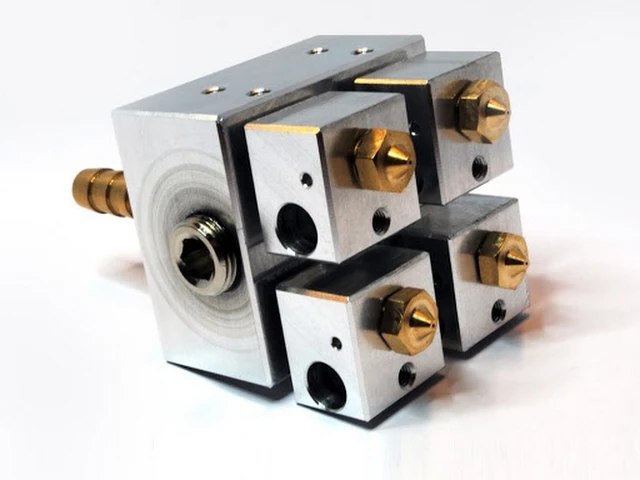
The four-extruder, water-cooled Kraken.
These come with their own problems — mainly ones of calibration. If the extruder has more than one nozzle, the nozzle tips must always be at exactly the same Z offset. Otherwise, the lowest nozzle will inevitably drag across the printed plastic deposited by the others. X and possibly Y offsets must also be set — but this is easily handled in software.
It would be nice if a single-nozzle solution existed — and now, it does. The folks at Mosaic have come up with one solution to the problem — create a custom-spliced filament and feed it into an unmodified 3D printer.
Note: The Palette+ referenced in this article is last year’s model. The new Palette2 and Palette2 Pro do the same job, but with some additional refinements. They also cost less. Progress!
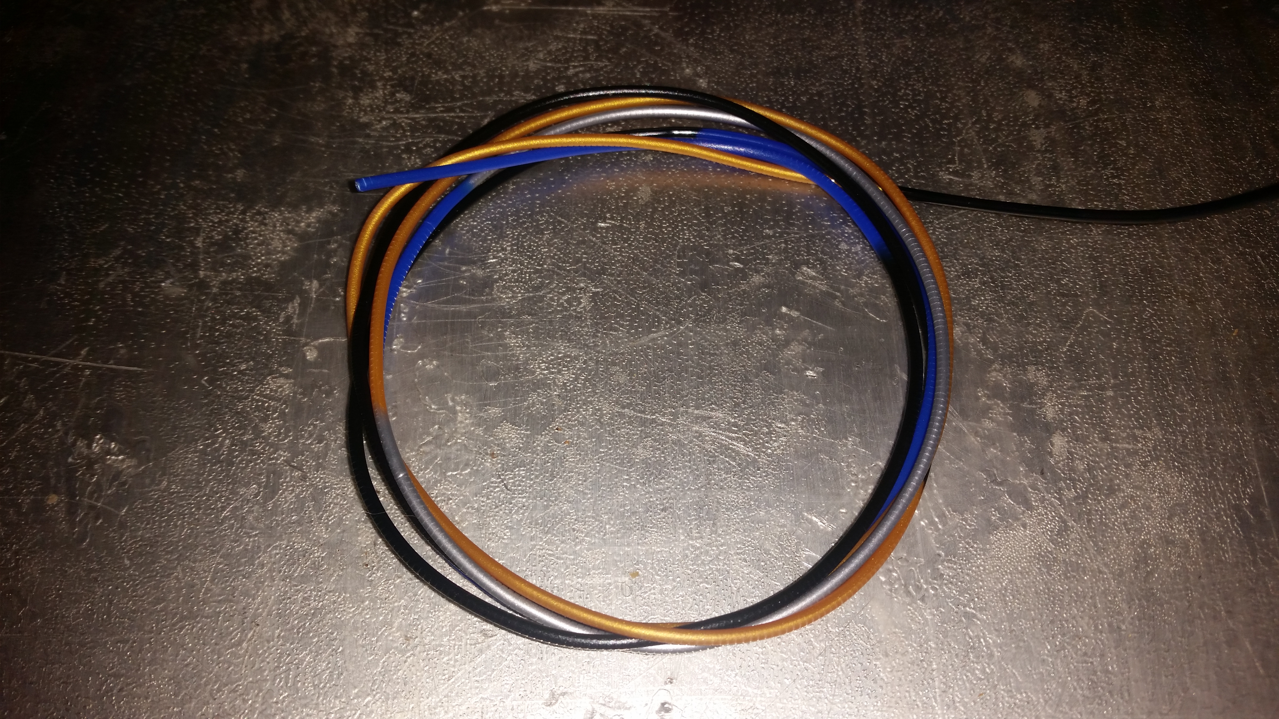
A sample of custom-spliced filament made by the Palette+
This is a subtler process than it seems at first. 3D printers vary slightly in the rate at which they use filament in a given print. This can even vary somewhat throughout the print. If a single extruder is used with a variegated feedstock and you want nice clean color transitions in your print, the color transitions need to be at the right point in the filament so the new color comes along just as the printer is getting ready to print a feature in that color. If the amount of filament actually used (as opposed to commanded) isn’t tracked by some closed-loop process, the position of transitions will inevitably drift, leading to increasingly inaccurate color transitions.
Worse, when the filament changes from one color to another, the process takes some time — longer if transitioning from dark to light filaments, shorter if transitioning from light to dark (generally speaking). Even if the color transitions happen at exactly the right locations, the change will generally be gradual and smeared, as the plastic in the hot end is gradually replaced.
Transition towers (or other purge methods) help with this. When transitioning between colors, the material near the transition is deposited into a sacrificial tower or block. This unfortunately wastes a lot of plastic, but it does ensure clean transitions as long as the transitions happen at close to the right time. The color smearing happens — ideally — on the transition tower, and not on the part being printed.
A (short) transition tower. (Corresponding part not shown.) As partial compensation for the extra plastic and time, some of these are genuinely beautiful.
The “secret sauce” to producing custom filament and transition towers involves two key parts: an autosplicer and custom gcode-processing software.
To combine up to four different filaments into a single stream, Mosaic’s Palette+ autosplicer uses seven stepper motors, a heater block, various sensors, a microcontroller, and custom-machined guides to precisely cut and splice the filament as instructed by the Chroma software. Four filaments enter; one combined stream leaves. It’s over-engineered as hell. This is not just engineering, but art. Fittingly, it’s housed in a very solid enameled stainless-steel case. Just don’t drop it on your foot. It’s a beast.
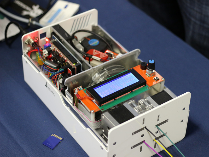
The Palette+ autosplicer, with its cover off.
(Image from Hackaday.com)
As an example of how the process works, here are the steps needed to produce a four-color print, using Sketchup for modeling and Simplify3D as the slicer.
The first step is to produce separate .stl files for each material of the process. These .stl files should not overlap geometrically in any places (since two different materials can’t occupy the same point in space.) Support requirements apply to the union of all of the materials, however. It’s OK if parts of one or more colors appear to be floating in midair, as long as they will be supported by other colors in the final print.
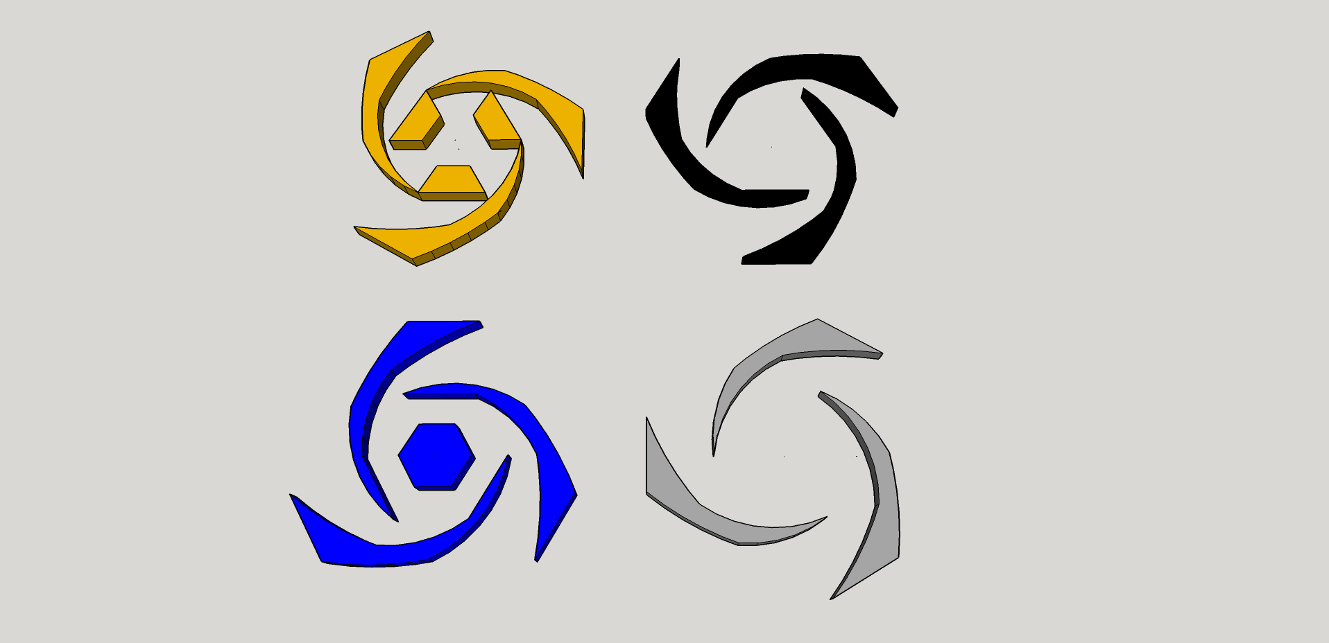
The four pieces of the model, separated.
These separate models are then made into groups and brought together in their correct final arrangement. This gives the resulting .stl files a common origin, so they can be easily combined in S3D. (One trick is to create the files with a uniform spacing of something like 50mm or 100mm, so moving them back when done is easy.)
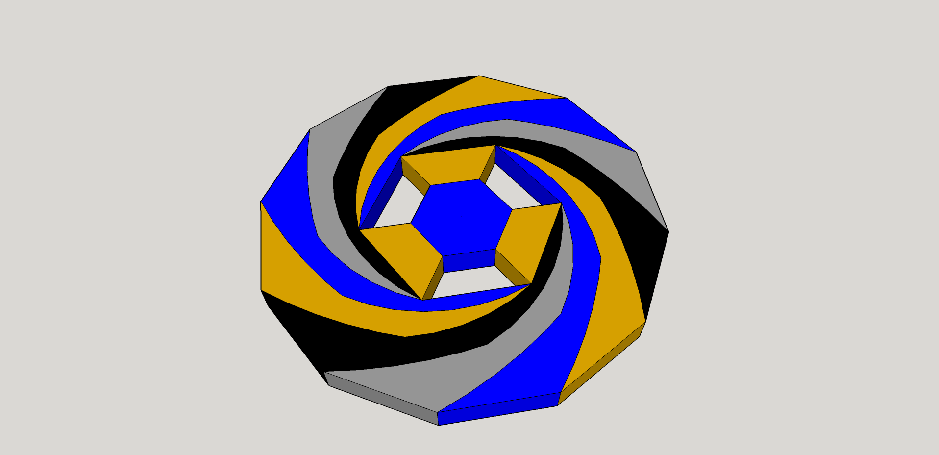
The pieces of the model, with a common origin point.
The four models are then exported, one at a time. It’s a good idea to label them with the intended colors at this point, since the next step is to assign a separate process (and tool) to each of the models. This is what will tell Chroma which filament to use for which part. The printer has only one extruder, of course, but Chroma will use the tool information to know when the color transitions happen.
Next, the four models are imported into Simplify3D. They will probably be lined up in a row. Hold Shift and click on “Center and Arrange,” and they will all snap to the center. Make sure they look like they are correctly aligned, with no missing pieces.

Checking the fit in Simplify3D. (Those holes are intentional.)
The next step is to create four (usually identical except the tool number) processes in S3D. These should each use a different tool for the extruder (usually, 0, 1, 2, and 3 respectively.) I like to keep the rest of the settings the same. You especially should match layer height, bed temperature, flow rate, and other settings which could cause incompatibilities.) Assign each process to exactly one of the models with the “Select models” button at the bottom left of the dialog box. When all four are done, preview the print and choose to color by process/tool. If it looks right, save the .gcode file — but don’t hit Print just yet.
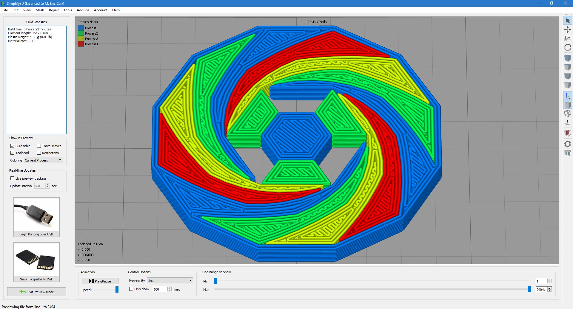
S3D preview, showing the four processes.
Now the first step is done — but we still need to make the transition tower and calculate the lengths of the splices for the Palette+ autosplicer. This is done in Chroma — special postprocessing software created by Mosaic for the Palette+ and other splicers.
In Chroma, click on Load Model and select the .gcode file you just made. Chroma will pause and analyze it for a few moments. When finished, it will display a preview of the model plus a transition tower. Clicking on the colored circles next to the four material selections at the top will allow you to change the colors of the model. (These serve to inform you and Chroma which colors are which — you, so you can load the correct filaments, and Chroma, so it can estimate how long the transitions need to be, based on the starting and ending colors. The splicer itself can’t tell colors or materials apart; differences are specified here manually.)
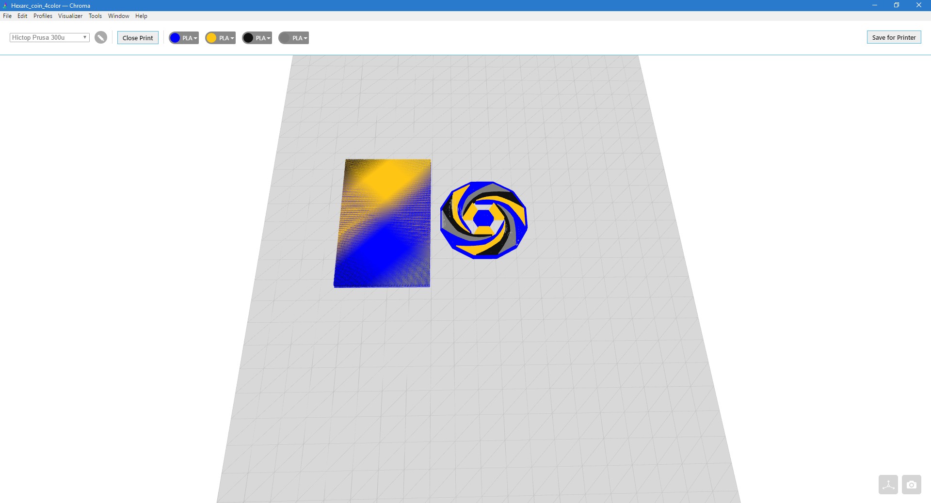
Planning the colors and transition tower in Chroma. (The same size tower can serve for multiple copies of a part.)
This not only helps you visualize what the final print will look like, but gives Chroma some information about how long to make the transitions. Going from light to dark filament happens quickly, for instance — but going from dark to light can take more time, as the darker color is visible for much longer.
When you click Save for Printer, Chroma will output two files: a file ending in .msf for the Palette+ autosplicer, and a modified .msf.gcode file to be printed. The .msf file is loaded onto a SD card to be put into the Palette+, since the Palette+ only has USB support for firmware upgrades, and is basically a standalone unit. Once the SD card is loaded and the file is selected under the Multicolor menu, the Palette+ will start producing filament after a few minutes’ warm-up time.
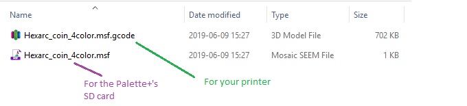
The .msf file goes on the Palette+’s SD card. Print the new .msf.gcode file, not the original one!
The .gcode file needs to be printed as usual — via SD card or Raspberry Pi or whatever. Simplify3D can still be used to preview the print in real time, provided you reload the new .gcode file using the “Preview .gcode file” option in the File menu. (The .msf script file controlling the autosplicer will expect the extra usage from the transition tower, as well as the included commanded pauses, so don’t print the original .gcode file.)
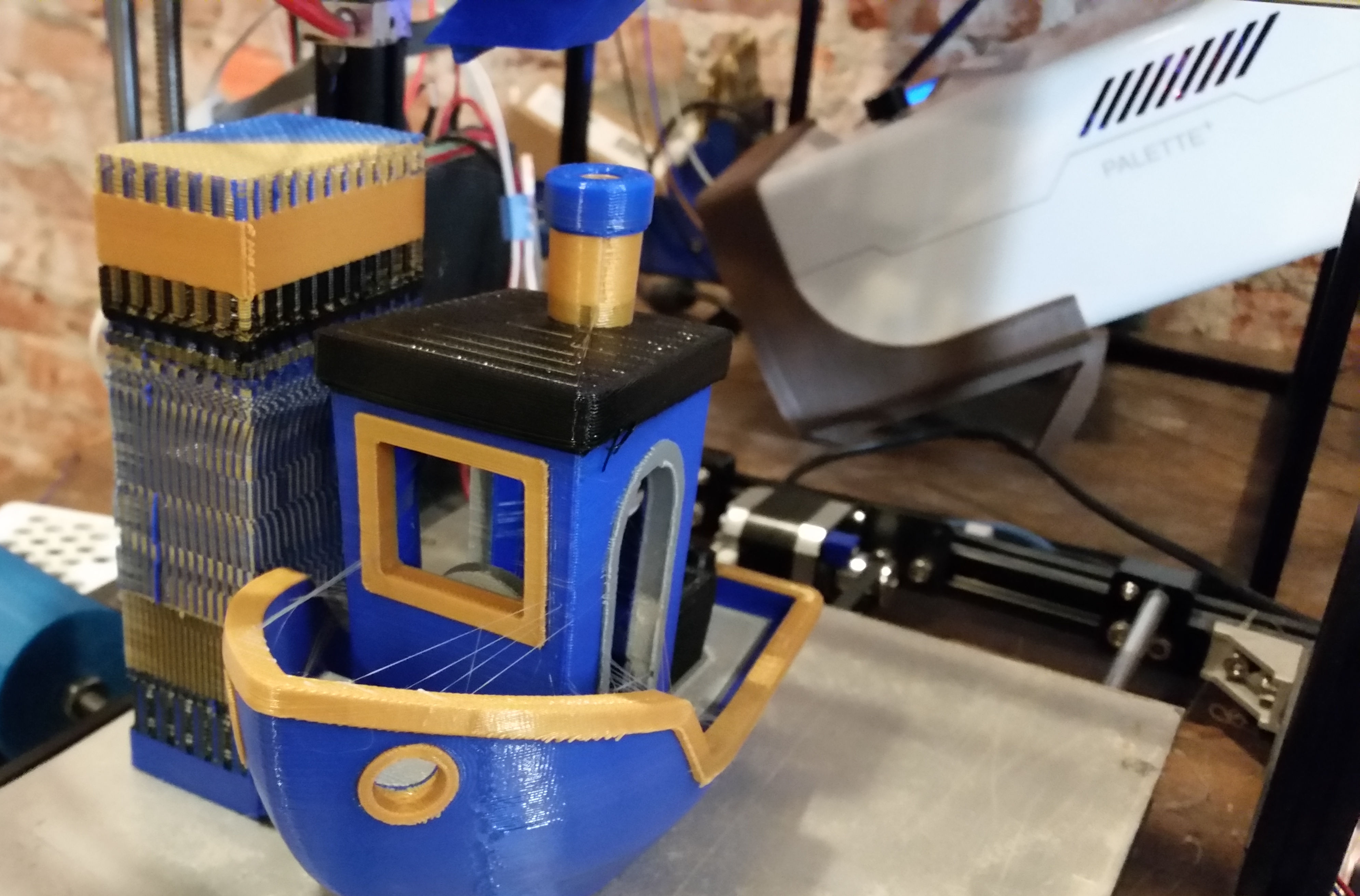
Once the .msf.gcode file is ready to print, the filament is loaded into the printer, passing through a distance measuring device to precisely monitor filament usage. The Palette+ will guide you as to the correct length of filament to feed into the printer. It will also judge how good a job you do; apparently an 0.3mm loading error (well within tolerances) is “Superb” loading. (I think I recall it deeming some of my first tries merely “acceptable.”)
The printer and splicer will then work together to produce the right lengths of each color of filament: calibrated pauses are built into the .gcode, causing the printer to periodically stop using filament for a few seconds at a time. The Palette+ detects this and uses this information to keep track of where the printer is in the print. It then adjusts the amount of filament produced so the transitions happen where they should.
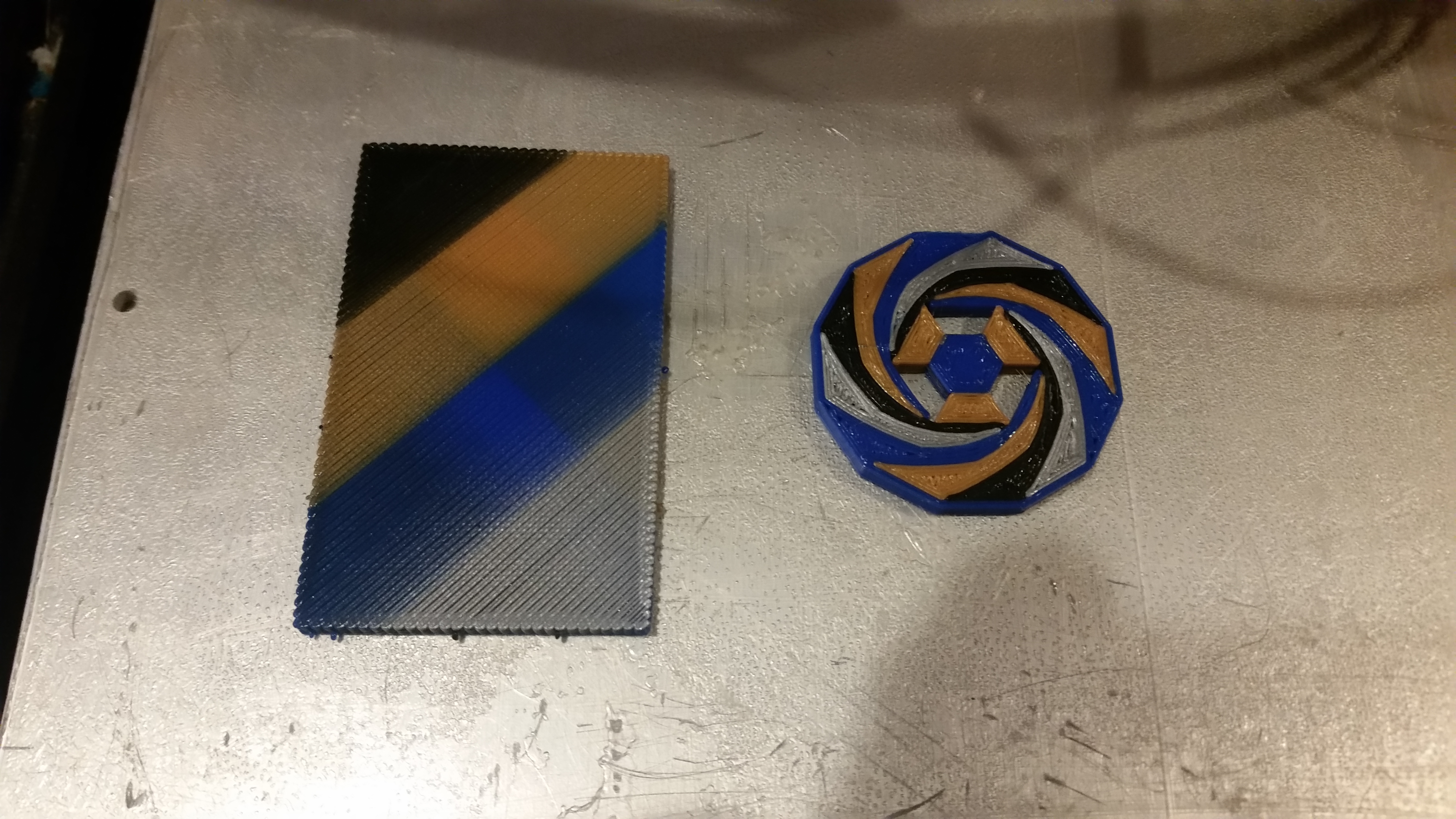
The coin and its transition “tower.” (These are always the same height as the last color transition in the model.)
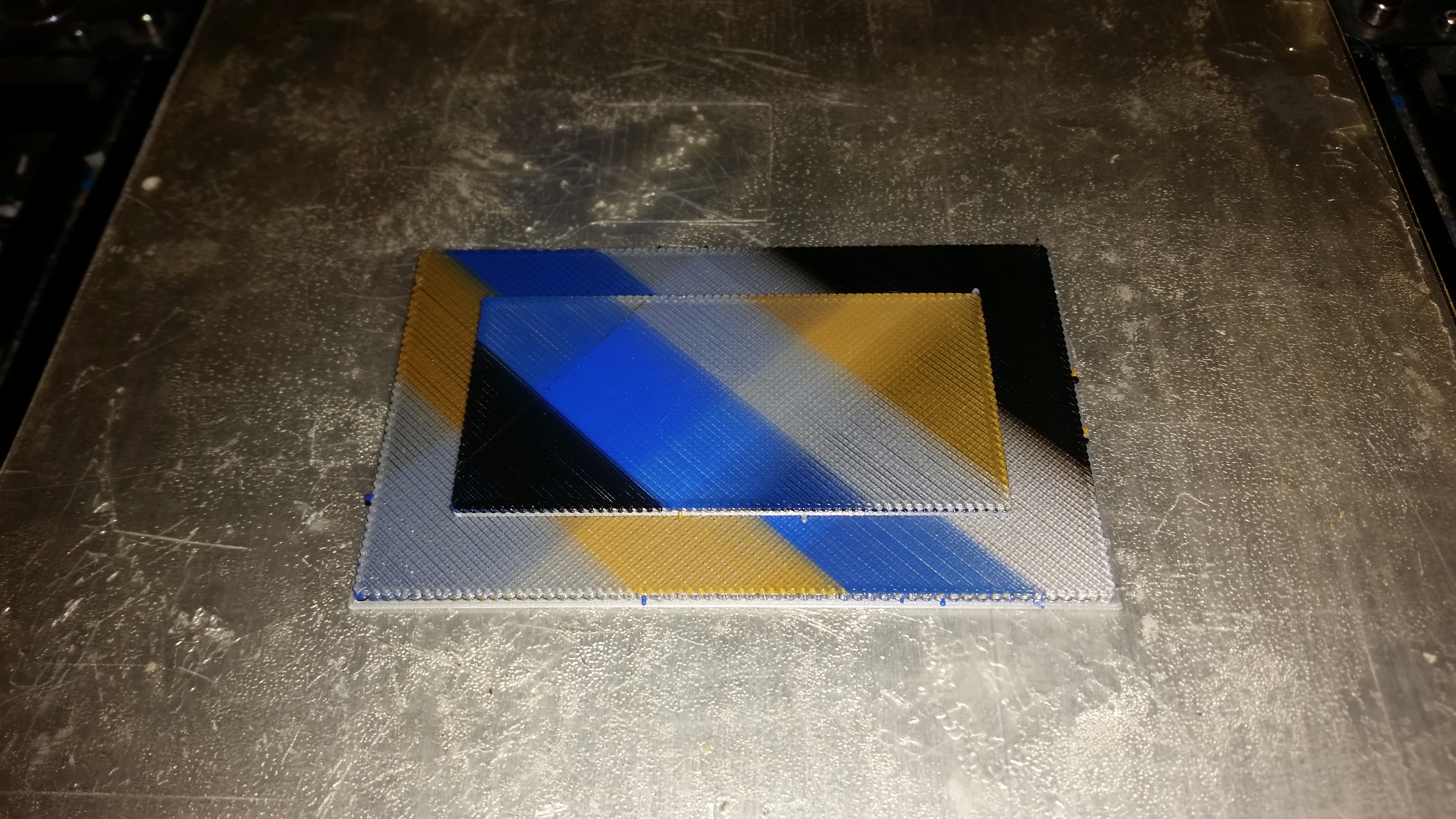
The process is definitely more involved than for single-color prints, but the results can be impressive.
Benchy Of Unusual Size.
It’s a surprisingly reliable process, if a bit complicated. Once I figured out that the filament has to stay dry in order to splice reliably, the Palette+ has been one of the most reliable parts of the printing process. (The new Palette2 does have USB control capability when used with the new Palette Hub.)
Happy printing!
