
Sometimes, it helps to state the obvious.
Kirchhoff’s Voltage Law (KVL) and Kirchhoff’s Current Law (KCL) are two of the most important ideas in electronics — right up there with Ohm’s Law itself. When they are first encountered, they seem almost too simple to be useful, and you could be forgiven for thinking that Kirchhoff moonlighted as Captain Obvious. But useful these ideas are, when used to write equations that describe the behavior of an electronic circuit.
KVL states that the sum of voltage changes around a closed loop — any closed loop — is zero. With just a little reflection, it’s obvious that this must be true. Otherwise, you could simply go around the loop as many times as you want, producing arbitrarily high voltages. Voltage-wise, if you get back to the same point, you’re also back to the same voltage.
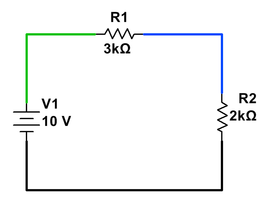
The voltage across the resistors will add to 10V.
Kirchhoff’s Current Law is similarly straightforward. For DC circuits, the current in to any given node must equal the current out of the node. (That is, we’re not allowed to store, create, or destroy electrons.) Equivalently, the total current flowing in to (or out of) any node must be zero.
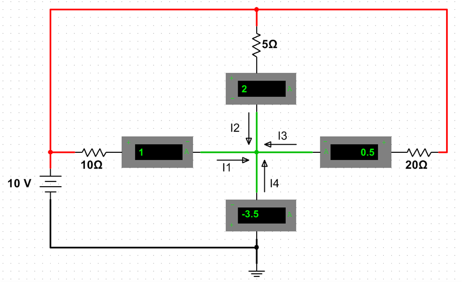
Three currents flow in to the center; their sum flows out.
By expressing these ideas as equations relating voltage, current, and resistance, we can solve systems of equations to find currents and voltages in each part of the circuit.
For example, consider the following circuit:
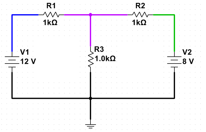
We can describe any DC current flow in this circuit in terms of two quantities: I1, which we will consider to be the current flowing clockwise in the left loop; and I2, which we will consider to be the current flowing clockwise in the right loop. (We may well get a negative number — or zero — for one or both; this would mean the current is flowing counterclockwise, or not flowing, respectively.)
With this convention, KVL, and Ohm’s Law, we can write the following equations:
(Left loop) 12V – 1000R*I1 -1000R*(I1-I2) = 0
(Right loop) 1000R*(I1-I2)-1000R*I2-8V=0
Solving these equations (by algebraic methods, or these days by an app using linear algebra), we get: I1=5.33mA and I2=-1.33mA. So I2 is actually flowing counterclockwise, which makes sense when you think about it — if V2 were disconnected, the center node would be at 6V. Since we’re connecting an 8V Thévenin source to it, current will flow into it.
Math isn’t a secret code. It’s the language of Nature.
