CircuitJS

Finding myself teaching an introductory Circuits course without (at least as yet) an institutional MultiSim license, I was looking around for alternatives and came across CircuitJS, originally created by Paul Falstad.

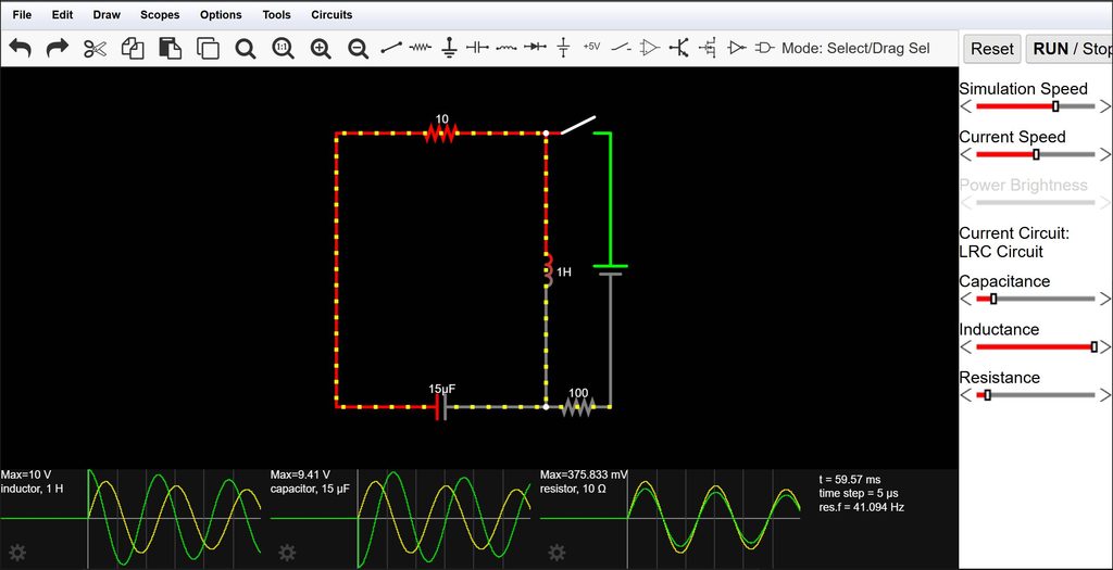
CircuitJS, running the default LRC circuit simulator.

CircuitJS’ peculiar drag-to-draw-the-component placement style takes a little getting used to, but then again, so does MultiSim. Once you’re familiar with it, though, it’s easy to use (press R to place a resistor; press W to place a wire etc.) I’m not sure I’d use it for circuit analysis (we already have various flavors of SPICE for that anyway), but it’s certainly a very useful tool for education — particularly the way it allows for visualization of current flow using moving yellow dots and relative voltages using color (Green/Grey/Red). Students can build a circuit, see how the current flows through it, and then modify it dynamically and see the resulting changes.

The default LRC simulation provides a good example of this. The circuit starts off with an initially charged capacitor, which provides the energy to set a series LRC circuit oscillating. Energy is traded back and forth between the capacitor and inductor, with the resistor converting part of it into heat on every cycle. The resulting damped sine waves (voltage and current) can be seen in the analysis below the circuit, synchronized with the movement of the “electrons” in the wires of the schematic.

It’s even available as an open-source, downloadable JavaScript app.

Posted in Analog, Digital, Electronics, Internet, Resources, Tools | Leave a comment

Mystery Directional Device

Another trip up North, and another weird and wonderful device to investigate!

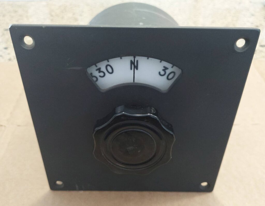
On a recent trip up to Maine, I came across a heavy device with a single knob that controlled a heading dial. (Dials marked 0-360 are almost always directional — and when they have 0, 90, 180, and 270 replaced with “N,” “E,” “S,” and “W,” it’s pretty much confirmed.)

The front panel of the mystery device

Turning the dial to S and looking in towards the shaft at what must have been an awkward viewing angle in its original mounting, I could see “CLB Mfg., Inc. Chula Vista, CA”

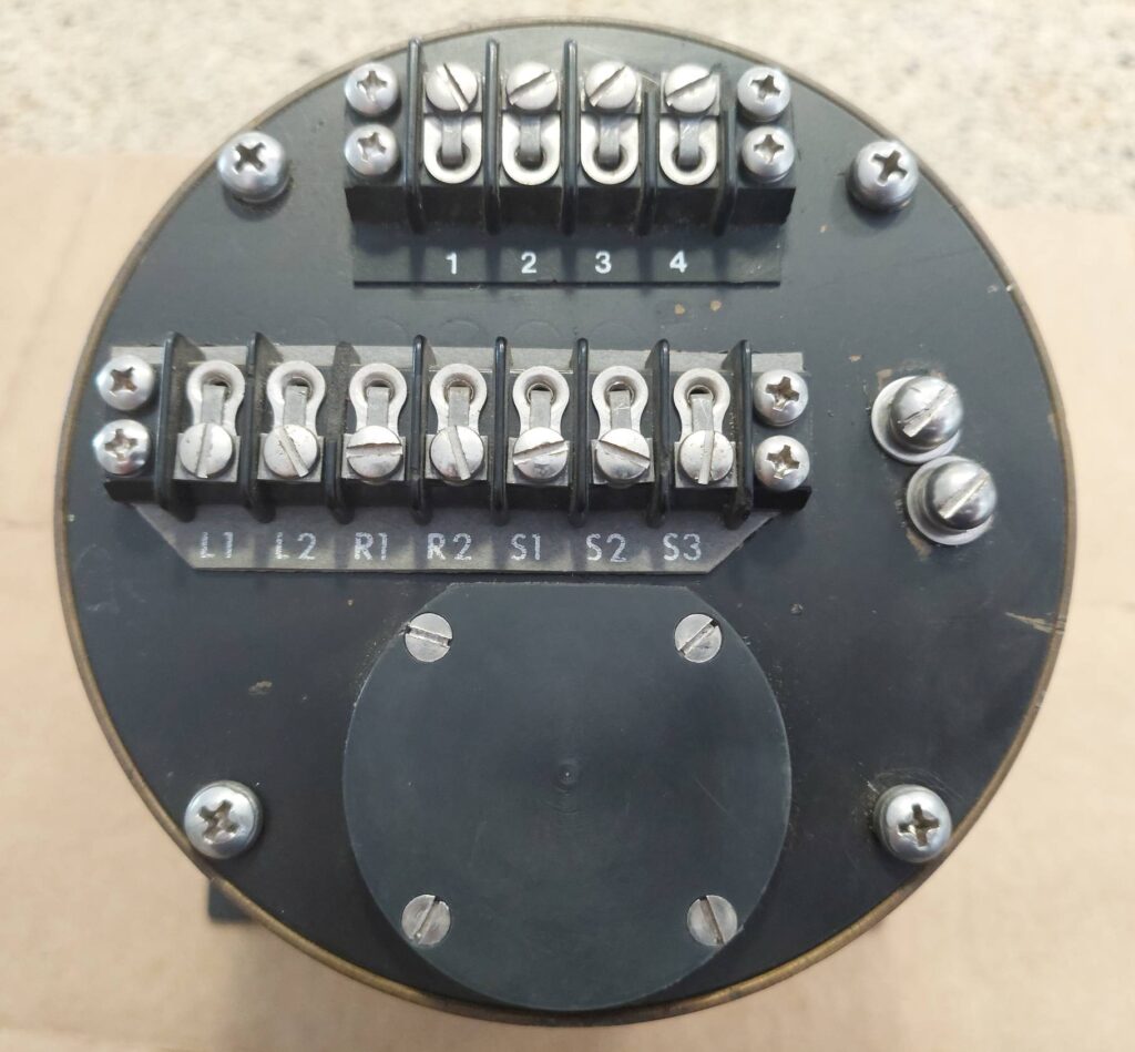
Looking at the back, I realized this had to be more complex than just a simple dial indicator. There were lots of connections — a set of what looked like three-phase windings, as well as “L1/L2” and “R1/R2” and whatever the heck terminals 1-4 are. Maybe L1/L2 and R1/R2 are Left and Right? For five bucks, how could I go wrong?

The back of the Mystery Device.
Whoa. Maybe it’s some kind of antenna rotator control?

Once I got it back to my folks’ place and could look at it more closely, I first tried to figure out what the electrical connectivity of the connections were. 1/2/3/4 were pretty clearly in some sort of Y configuration, with 4 as the common/center, and about 600 ohms from there to each of 1, 2, and 3. Symmetric coils, maybe? L1/L2 had some resistance between them, as did R1/R2. S1/S2/S3.

I decided to open it up to see if I could figure out anything.

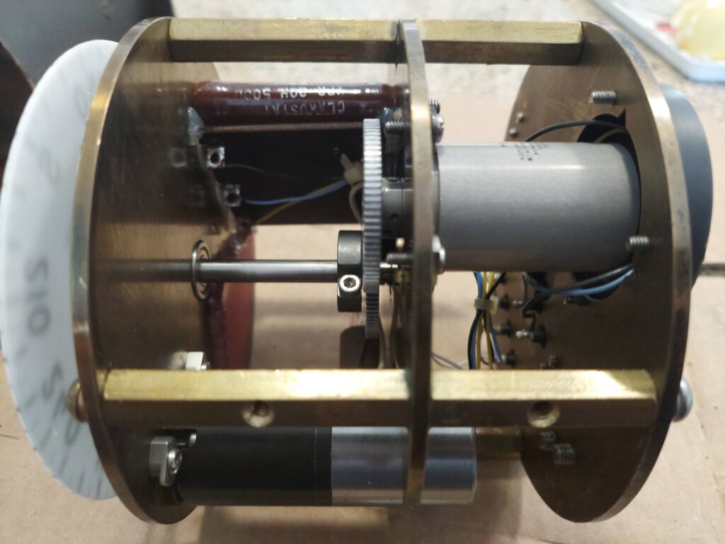
Side view of the inside of the Mystery Device.
Wait — the transducer I was expecting, but not a motor!

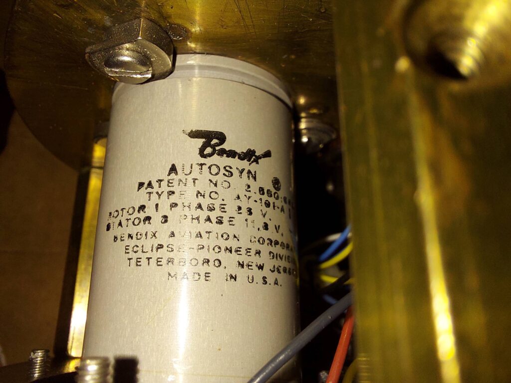
Seeing the inside just made it look weirder. There’s a Bendix “Autosyn” resolver geared 1:1 with the dial — but there’s also a 3-phase geared motor that can drive the shaft through a friction coupling. L1/L2 turn out to be Lamp connections; lighting the lamp would backlight the dial in red, for night operations. R1/R2 are the rotor connections to the Bendix resolver (which works with S1/S2/S3.) 1,2,3, and 4 are the Y-wound connections to the 3-phase motor, which seems to not have any positional feedback itself; the loop must be closed in external electronics, using the results from the Bendix.

The Bendix “Autosyn”. Must be some kind of analog resolver…?

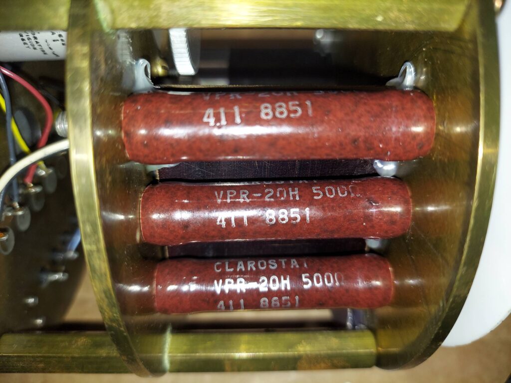
The motor winding connections are in phase with some beefy Clarostat 500-ohm resistors; these may be designed not only as series ballast resistors for the (completely unmarked) three-phase motor, but must also provide a nice, cozy warm environment for the mechanicals.

Beefy 500-ohm resistors on each motor phase…

I’m still not sure exactly what it is — ChatGPT’s take on it is that it’s probably some kind of marine course selector/readout device, capable of both setting a course manually as well as having an autopilot device make course corrections via the 3-phase motor.

I guess the next step is a VFD to power up the 3-phase motor and see how it works…

Posted in Analog, Electronics, Mechanical, Reverse Engineering | Leave a comment

Digilent Analog Discovery 3

In conjunction with a recent KEEN engineering workshop, I was provided with a complimentary Analog Discovery 3 kit by Digilent. Although I already have a reasonably functional electronics lab at home, the AD3 nonetheless is an intriguing tool to have in the go box, building lots of useful functionality into a single USB-C device.

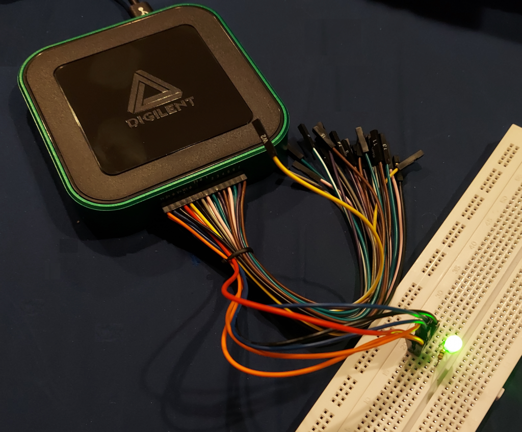
A Digilent Analog Discovery 3 kit, set up to trace an I-V curve for a green LED.

The idea behind the AD3 is that hobbyists, students, engineers, and experimenters can put together a huge variety of electronics experiments without having to have tons of equipment. One more-or-less pocket-size box can do it all — two programmable DC power supplies; two oscilloscopes not tied to Ground unless you want them to be; two waveform generators, sixteen digital I/O which can be used as a multi-channel logic analyzer / protocol analyzer, and a neat Waveforms software package that ties it all together into a virtual instrument suite. If that’s not enough, there’s a scripting mode where you can control various functions based on the data returned from others.

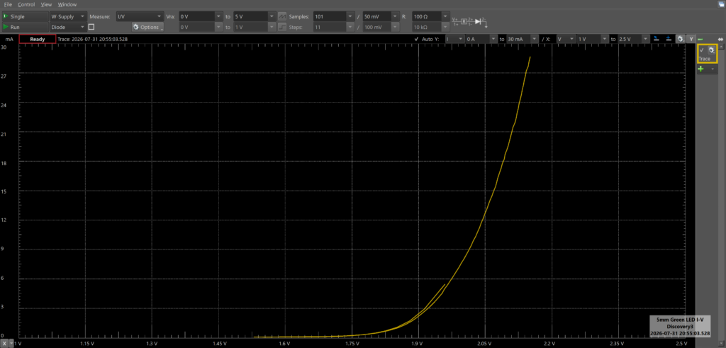
A Waveforms screenshot, showing the I-V curve for the green LED in the circuit above.

As part of the KEEN workshop, we were given “mystery circuits” and tasked with using the AD3 to investigate what components they contained. Even without the purpose-made component adapter, it’s straightforward enough to connect the device under test (DUT) and a series resistor, and wire the experiment up so the AD3 can provide controlled voltages to the circuit while monitoring the current through the resistor (and therefore through the DUT). After a little experimentation, we determined that the device was a red LED in series with a resistance of a few hundred ohms. (There’s even an I-V curve tracer function that makes this easy.)

Setup of the AD3 is straightforward; a breakout connector is provided to turn the onboard 30-pin connector into thirty female DuPont connector wires. (Long male-to-male pins are provided to facilitate breadboard connections.) Perhaps it was a quirk of the device I got, but inserting the breakout connector took significantly more force than I was initially willing to risk, until the workshop instructors told me they had a spare on hand, should it break. After using a ridiculous amount of force (I estimate 30-50 lbs or so), the connector seated, and fortunately, subsequent uses of the connector don’t seem to require any additional Feats of Strength.

If this hadn’t been provided for free, I’d still be impressed, but perhaps not enough to justify the $379US price tag, given that I already have discrete devices that can do most or all of what the AD3 does, if not nearly as easily. The AD3 does have all of the basic electronics lab functionality you need, but is necessarily limited in terms of power supply voltages and currents, and oscilloscope / waveform generator bandwidth. When testing the self-resonance of capacitors, the Waveforms software started to notify of bandwidth limitations when testing at 20-25MHz. While this is plenty for a basic electronics lab, even inexpensive microcontrollers like the ESP32 run at much higher speeds (240MHz) these days.

Digilent has always had a student-centric focus, though, and with a healthy student discount, the AD3 could make a great personal starter lab. With departmental funds, it’s also a great way to put together interesting, useful electronics experiments for a university or college curriculum.

It’s absolutely going in my electronics go bag, provided I have a laptop along to run it.

Posted in Analog, Tools, Toys | Leave a comment

True Immersive Gaming

Computer gaming is about to experience one heck of an upgrade.

The advent of Large Language Models (LLMs) and Context Engineering has made coding far faster and easier, allowing anyone to create at least basic apps simply by asking for it in sufficient detail, given a sufficiently advanced model and enough tokens.

This is already profound magic in its own right, but LLMs can do much more than just code. With the right prompts, they can perform countless language-based tasks. Including storytelling. And this opens the door to the ultimate kind of Choose-Your-Own-Adventure stories: ones where your choices influence the world of the story, and the storyteller changes the tale accordingly.

I’m pretty sure that ChatGPT and other frontier models could tell a good interactive story. But can locally-hosted language models that can run on a reasonably-priced modern PC?

To find out, I coded got Codex to code a Python script to set up a LLM with the tools needed to be a “Storyrunner”. Given basic instructions on how I wanted the app to work, GPT5.5 (as the Codex agent) put together an effective sketch, saving the game state in various files. On each storytelling turn, the model is given the initial prompt plus a game journal which details everything about the current game that is known to the storyteller / Game Master. In theory, a different model (certainly a different instance of the same model) could handle each turn, reading all of the information about the current state from scratch and then deciding how to direct the next step of the story, what things and events to describe, and so on. There is a Player Journal which details everything known to the player, and a Game Journal (full of spoilers if the player were to read it.)

Model choice seems to matter a lot, and models which excel at coding don’t necessarily always make good storytellers. OpenAI’s gpt-oss-20b is a good all-around local model (and happens to fit nicely in a 12GB RTX4070 GPU). But its adventures are all AI-slop knockoffs of some generic Thomas Kinkade-meets-Tolkien fantasy world. Put lighthouses, globes, clocks, windmills, and foggy beaches on your Bingo card and you’ll win every time.

Google’s Gemma-4-31b, however, seems to be pretty capable. I’m already several collaborative pages into a “strange adventure” (as the initial prompt requested) in a foggy land (okay, first mark on the Bingo card) where Time seems to ebb and flow erratically, following something called the Drift. The feeling is one of conversing with a skilled storyteller, but communicating via carrier pigeon: the local Gemma4 model takes about ten minutes per response.

This is only going to get better, faster, and more immersive. Expect the next generation of video games to have NPCs, companions, and even simple mobs which can react intelligently (or authentically unintelligently), remember players and their actions taken in context, and develop opinions, form friendships, hold grudges, and all the rest. Gameplay will be far more immersive and dynamic than ever. Rather than having to hand-code scripts for characters to recite based on a few player choice possibilities, players will simply talk to characters, who will respond based on that character’s worldview and memories.

Imagine going on a riverboat trip with Mark Twain.

I love living in the Future.
Posted in Coding, Current Events, Games, Machine Learning / Neural Networks | Leave a comment