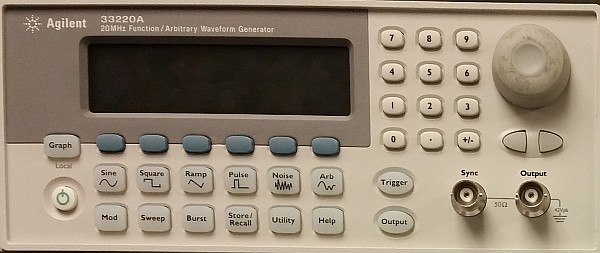
A signal generator is a very useful thing to have in an electronics lab. These devices can generate sine, square, and often many other waveforms, at a given amplitude and frequency. Just the thing for measuring frequency response in filter circuits — or generating a clock signal to drive a digital circuit.
However, there’s a hidden “gotcha” on many of these devices. They don’t actually measure the amplitude of the signal they put out. They rely on an internal voltage divider and calibrated amplifier stage, and assume a given load impedance — typically either 50 ohms or high-Z (effectively, an open circuit). If the load impedance matches what the signal generator has been set for, all is well, and the amplitude will be more or less correct.
If the load impedance is significantly different from the menu setting on the signal generator, though, the amplitude can be off by as much as 100%. For example, if a signal generator is set for 1.0Vpp at 50 ohm impedance, but is actually connected directly to an oscilloscope with 1Mohm input impedance, the actual output amplitude will be right about 2.0Vpp.
The moral of the story? Never trust a smiling signal generator — at least as far as impedance is concerned. Whenever you change the load impedance (which can happen by simply changing frequency, if you have a reactive component to the impedance), it’s important to actually measure the real output amplitude — for example, with a ‘scope.


