The Fitbit Ionic is a neat little device, capable of tracking various different exercises as well as providing continuous heart rate monitoring and sleep quality tracking. It is quite well-connected as well, with WiFi, BlueTooth, and NFC capabilities. It can stream music to Bluetooth headphones, sync exercise data over WiFi, and pay for your snacks via NFC.
The battery life is better than I expected, too. It will run for several days of typical use without charging. If I don’t use the GPS tracking feature much, it can sometimes go roughly a week between charges. It even sends you an email when it’s low on energy. Welcome to the future.
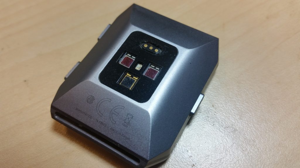
The one drawback, of course, is that (being waterproof) the Ionic uses a proprietary MagSafe-like connector for charging. And naturally there’s no information readily available about what pins are what. So if your Ionic’s battery is low and you don’t have its charging cable handy, you’re pretty much out of luck.
Time for some detective work.
I knew that the charging connector was symmetric; it will work in either orientation. So the two outside pins must have the same function. This, with the fact that the charging cables don’t look like they contain more than just wires, means that, in all likelihood, either the center pin is ground and the outer pins are 5V, or the other way around. If I were designing a watch like this, I’d go for one 5V pin in the center and two ground pins. Let’s try that, I figured.
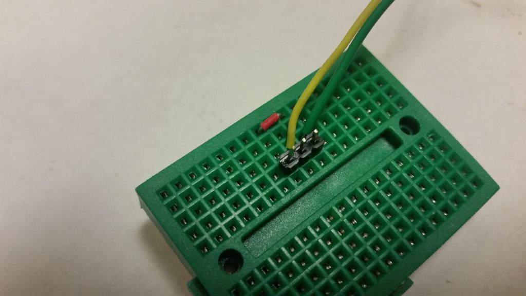
So I hacked together a small breadboard-based adapter and connected it to a current-limited lab power supply. (The current-limited part is important: if you get the polarity wrong and forward-bias a protection diode, you don’t want your power supply dumping three amps of current through it. That’s how the magic smoke gets let out. With the current limiting, the supply will back off on the voltage if too much current is flowing. This gives you time to disconnect it before anything gets too warm.)
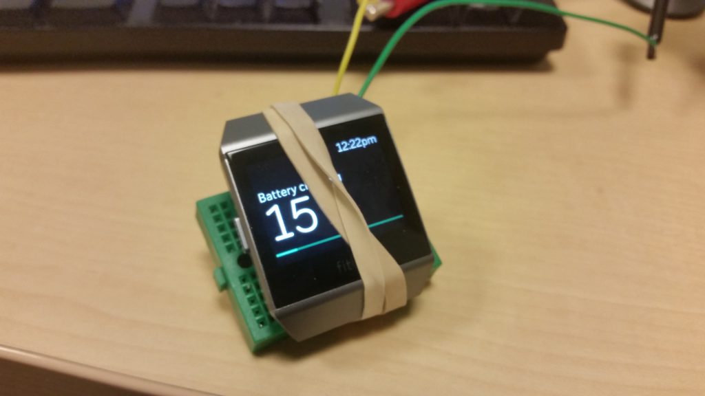
I limited the power supply to 300mA and gave it a shot. With a little adjustment to get it to sit on the pins properly, it works, drawing about 180mA at 5V.

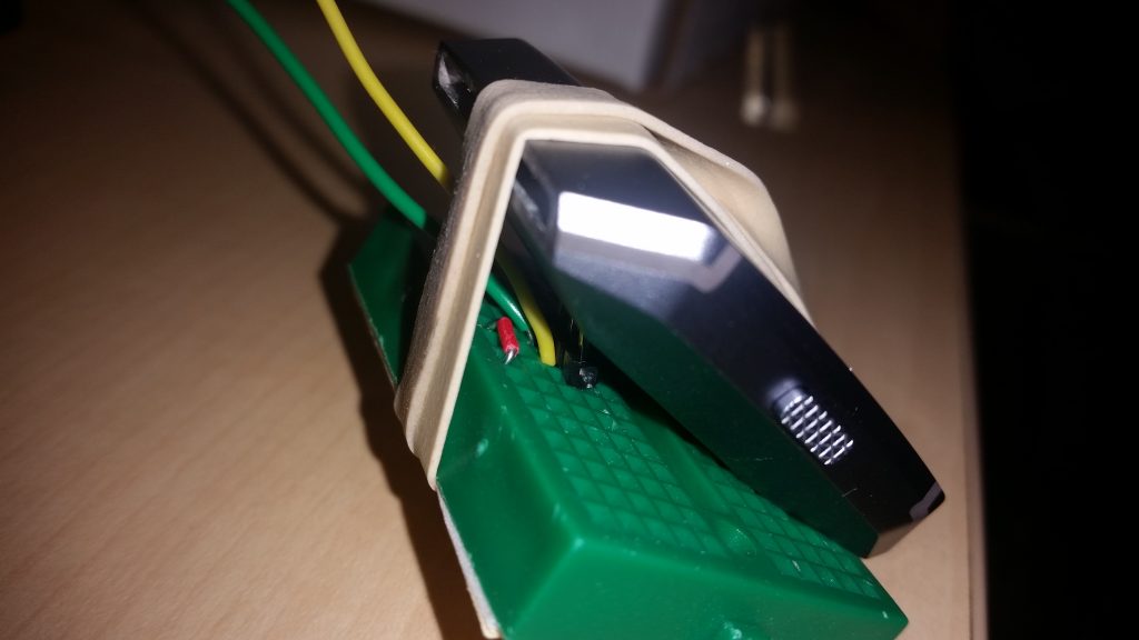
Details of the connections. The outer two pins are tied together and to Ground. The center pin is 5V.
The adapter itself is straightforward: Three standard row-connector pins, with the outer two bent slightly inwards to match the Ionic’s connector pitch. The outer two are connected together and to Ground (black, on a USB cable); the center pin is connected to a 5V supply (red, on a USB cable).
Disclaimer: Use this technique at your own risk; this is a hack, not an engineered solution. It worked for me, and properly implemented, should work for anyone, but will certainly void your warranty if you get it wrong (and maybe even if you do it right.)


