It’s well known that the 555 timer IC is a very versatile piece of technology. (The fact that it’s still being produced after nearly forty years attests to this.)
…but can it compute?
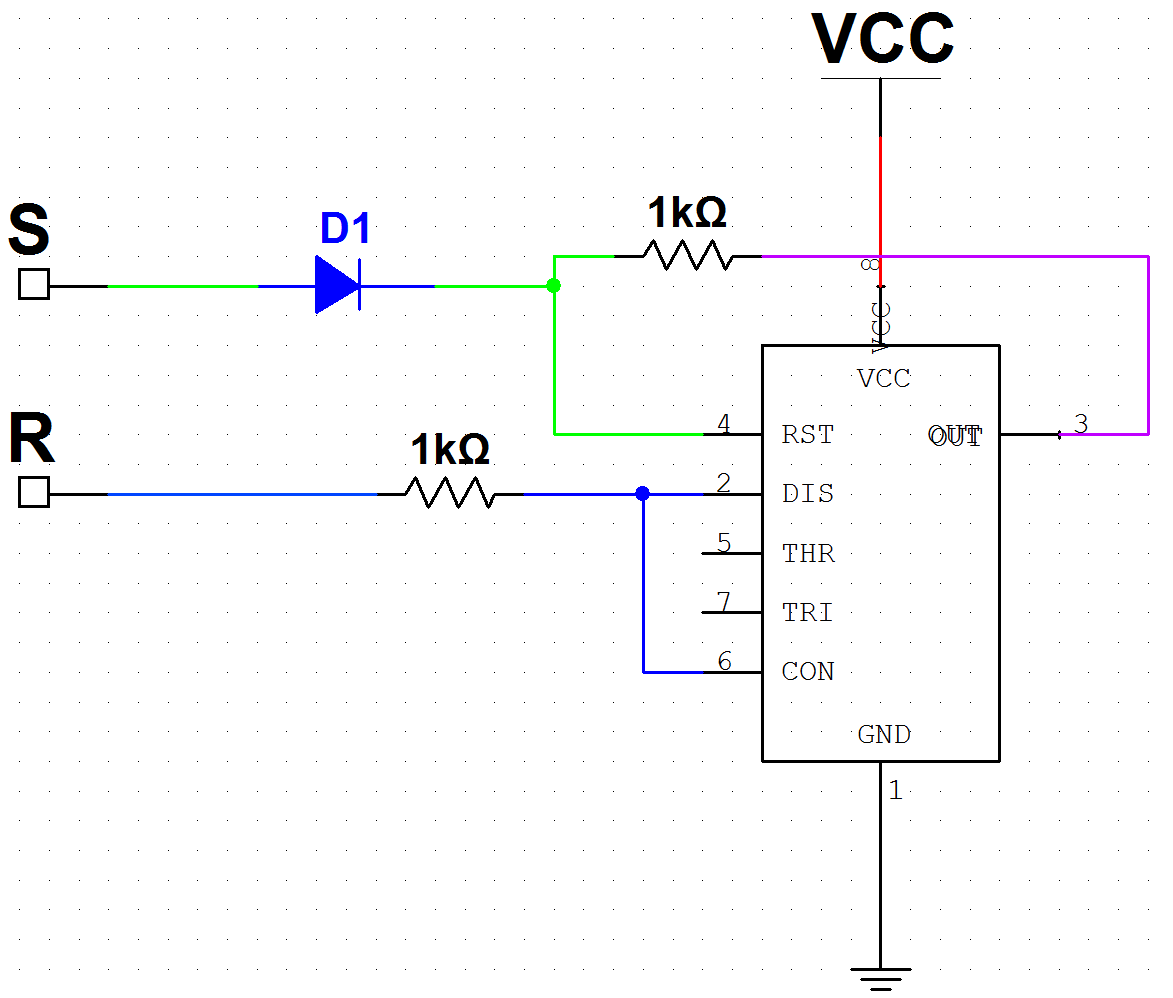
As it turns out, the native “A * ~B” gate (see “Boolean Logic with 555s“) can be made into a S/R latch, with the addition of a few resistors and a diode. (The 555 actually does contain such a latch inside it, but not all of the latch ports are exposed as pins.) The diode is needed to block a low (inactive) signal from the Set pin from resetting the circuit when it is in the on state. The reset resistor (connected to DIS/CON, not RST) may not be needed; this design was hastily done in time for the 555 contest and I went with the first implementation that worked.
This S/R latch circuit allows a 555 to function as one bit of static RAM. With enough 555s — and no other active components — a primitive (but Turing-complete!) computer can therefore be built, using only 555s! (For this implementation, I’m using diodes, which are technically active, but even these are not essential. Given enough 555s; S/R latches can be built from logic gates alone, which can be built from 555s, as demonstrated in another post. The diodes do help reduce the circuit size quite a bit, though.)
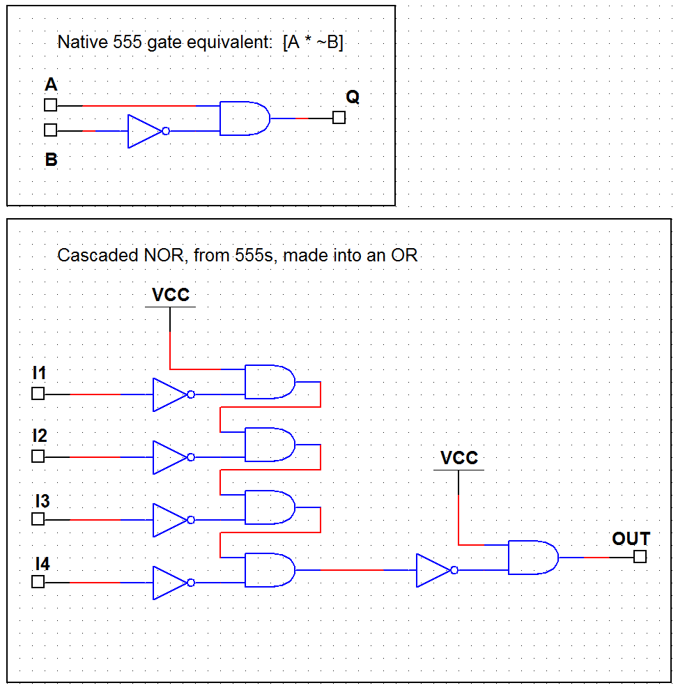
One tricky factor is the lack of tristate output functionality; the 555’s output is always high or low, never tristated. This can be mitigated by using OR gates (a NOR cascade with a final inverter, as shown below) to combine the various possible sources onto a single bus. As long as only one source is active at a time, its data will be carried through correctly — and no electrical contention (shorted outputs) is ever possible, even if more than one source does go active/high at one time. Multiplexing N outputs into a single line via OR logic therefore requires N+1 555s. (This could also probably be done with diodes and a pulldown resistor, but the eventual goal is an all-555 design.)
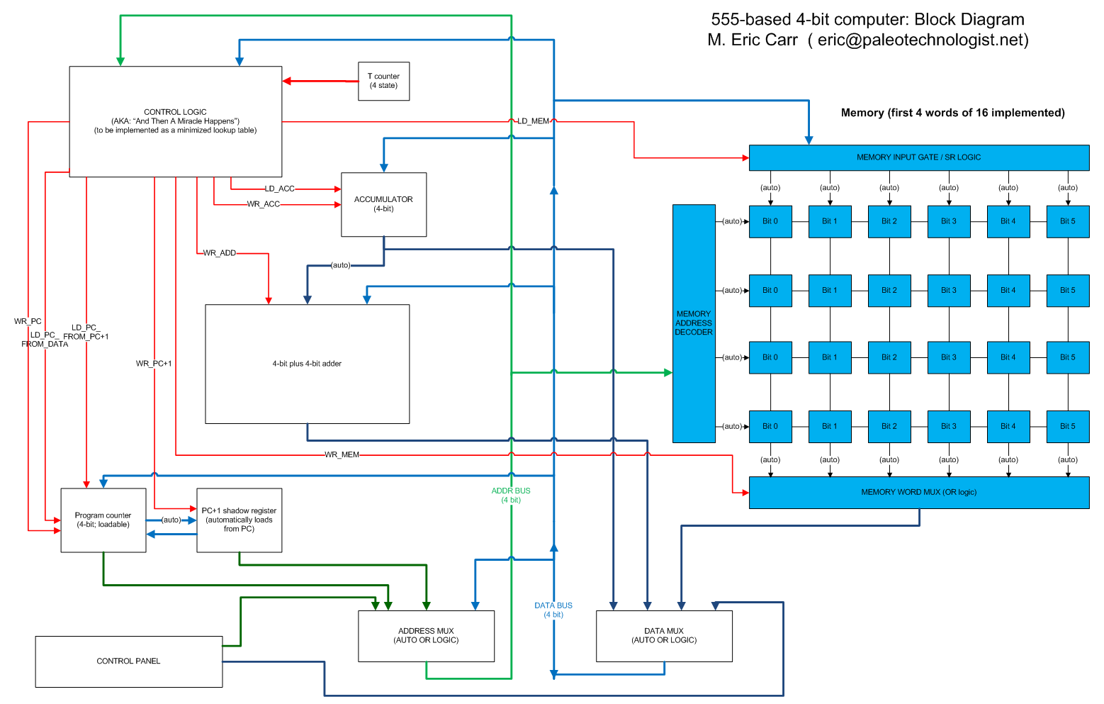
Since using 555s as logic gates is extremely inefficient in terms of space and wiring complexity, the computer design is necessarily quite simple. A six-bit word size allows for orthogonal instructions: 2-bit opcodes with 4-bit operands. This will allow for four possible operations, and 4-bit operands ranging from 0 to 15. Twenty-six or so 555s are needed for each word of memory, plus extras to combine them onto the output lines, so I have built just four six-bit words for the time being, rather than completing all sixteen possible memory locations. Another six-bit word for the accumulator has been completed, along with a four-bit word for the program counter. The 2-to-4 address decoder for the memory is complete (visible on the breadboard at the side). The rest of the control and processing logic is planned but not built at this point. Here’s the planned block diagram:
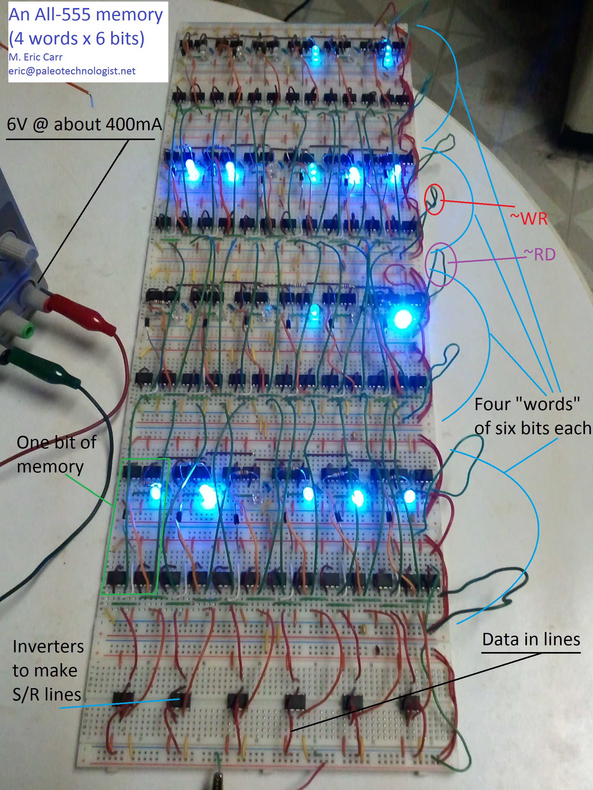
Here’s a picture of the memory subsystem:
Here is a video of the memory in action (storing several words of data). The LEDs show the state of the memory; with the addition of a (mostly complete) NOR cascade multiplexer, the memory will be capable of outputting its data onto a single data bus. With the addition of a (completed but buggy) address demultiplexer, the memory subsystem will be ready to take its place in the 555 computer.
Unfortunately, lack of time (I get to do a lot of interesting things at my day job, but they do seem to insist that I show up for work) has prevented me from completing the entire design in time for the contest — but the design is feasible. Hopefully, I’ll be able to have the whole thing up and working sometime this summer. If so, I’ll post the details here.


Pingback: Building a computer out of 555 chips - Hack a Day
Pingback: Building a computer out of 555 chips | You've been blogged!
I also designed a 555 timer CPU for the contest, but failed to implement it in time. It also relied on S/R latches, but I had problems implementing the program counter. I tried SR latches separated by inverting differentiators, but it proved too unreliable, and I wanted a more elegant solution than building one from 555 logic gates. Any ideas?
My architecture was very different from yours (one bit math, single instruction set), but if you’d like to compare notes, perhaps two different 555 CPUs will be built!
Hmm. A program counter should definitely be possible, since any basic logic gate can be made out of enough 555s. I haven’t made a program counter yet (haven’t had time to do much more on this project recently, unfortunately), but it sounds like a fun project. If I get something like that working, I’ll post it on this site. I also thought about a single-instruction-set machine (the ultimate in RISC!), but wanted to go with something just slightly more conventional (maybe MOV, ADD, SKP, and JMP or something.)
It is possible to make a quasi D-Type latch from a single 555 if I remember correctly. I chained these in series to make a binary counter with jam… only to find out they were doing rising edge detection instead of the required falling edge detection. In theory it is possible to use gate delay to make a falling edge detector (using 555s only) by comparing an output signal against a buffered output signal. I did not have any luck with this method, I hope it will help you though!
Pingback: Building a computer out of 555 chips | The Depot of Talk
Hey Im new to electronics but i learn fast i have been trying to build something very similar…
-I remeber reading some where about using diodes when connecting different chips (or somthing around those lines).
Whats the purpose for them to keep the voltage up. seeing that i was building mine with 2n222 npn transistors didnt think i would need to use diodes is this true.
-What are some of the sources that you used to help you build this or if you know any
Thanx
Basically, a diode allows current to flow in one direction but not the other. In other words, it will allow a high signal on one end with a low on the other, but not the other way around. In the example above, the diode keeps the output isolated from the S input. You could do this with another 555 instead of a diode (and there might even be a better way to make a latch with just 555s and no diodes; I’m looking into that.) Eventually, I’d like to make as much of the computer as possible without any components at all except 555s. (It will need some resistors, switches, and LEDs for the control panel, and might need some capacitors to clean up the power on the main boards, though.)