
Capacitors, the electronics textbooks would have you believe, are very simple devices. In their most basic form, they consist of two conductive surfaces separated by a thin dielectric (insulating) material.
Various different materials have been used over the years, from air to paper to tantalum and many more. One popular choice for dielectric material is mica (which is also used for heatsink insulators, since it conducts heat but not electric current.)
“Mica” capacitors have been made using metal deposition for decades at this point — the capacitors are much more reliable and stable this way — but the original mica capacitors from the early 1900s were simply pieces of mica clamped between two metal plates.
I don’t have the necessary equipment to attempt metal deposition, but old-school clamped mica capacitors don’t require very much in the way of equipment. The secret ingredient, of course, is the mica. While on vacation in Maine last month, I came across a large specimen for sale that looked like it might produce nice, clean sheets.
")
A chunk of mica, as it might be found in nature. (Click for larger.)
This is one of the nicest pieces I’ve seen. I don’t feel too bad about experimenting with it, though. The reason mica works so well as a dielectric is that the individual sheets are extremely thin — so very little is needed. (Single sheets from this one seem to be about 20-30um in thickness, although this is on the edge of what I can measure reliably with digital calipers.)

30um thickness, to something like one sig fig or so…
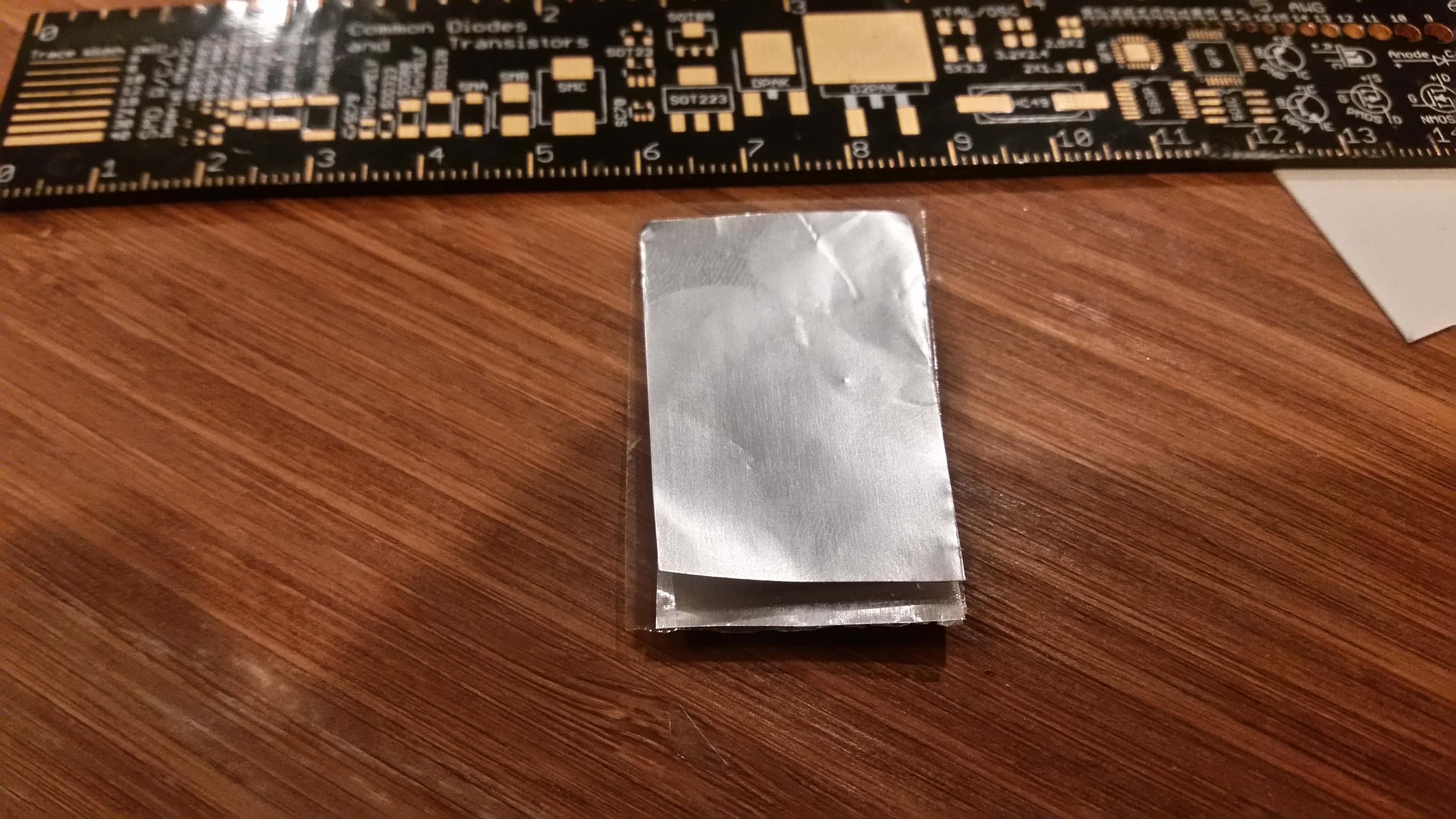
Using a razor blade and some patience, I was able to lift a layer of mica from the chunk. I then cut it to a roughly rectangular shape. Next, I made a template from an old business card that was slightly smaller than the piece of mica. I used this template to cut two pieces of aluminum foil, making sure they were slightly smaller than the piece of mica.

A single layer of mica (more or less). Click for larger.
The next step was to sandwich it all together. I used more pieces of business card to insulate the outside, allowing the use of alligator clips to clip on to the mica. I then connected the jumper cables to a component tester.
The inner part of the sandwich. The two metal plates must not touch.
The verdict: It works! The component tester shows a capacitor of roughly 80pF (and shows no component when one of the wires is disconnected at the cap.) The capacitance doubles to ~160pF when I hold on to the paper insulation — and almost quadruples again, increasing to nearly 600pF, when I squeeze it together. Time to 3D print a compression jig!
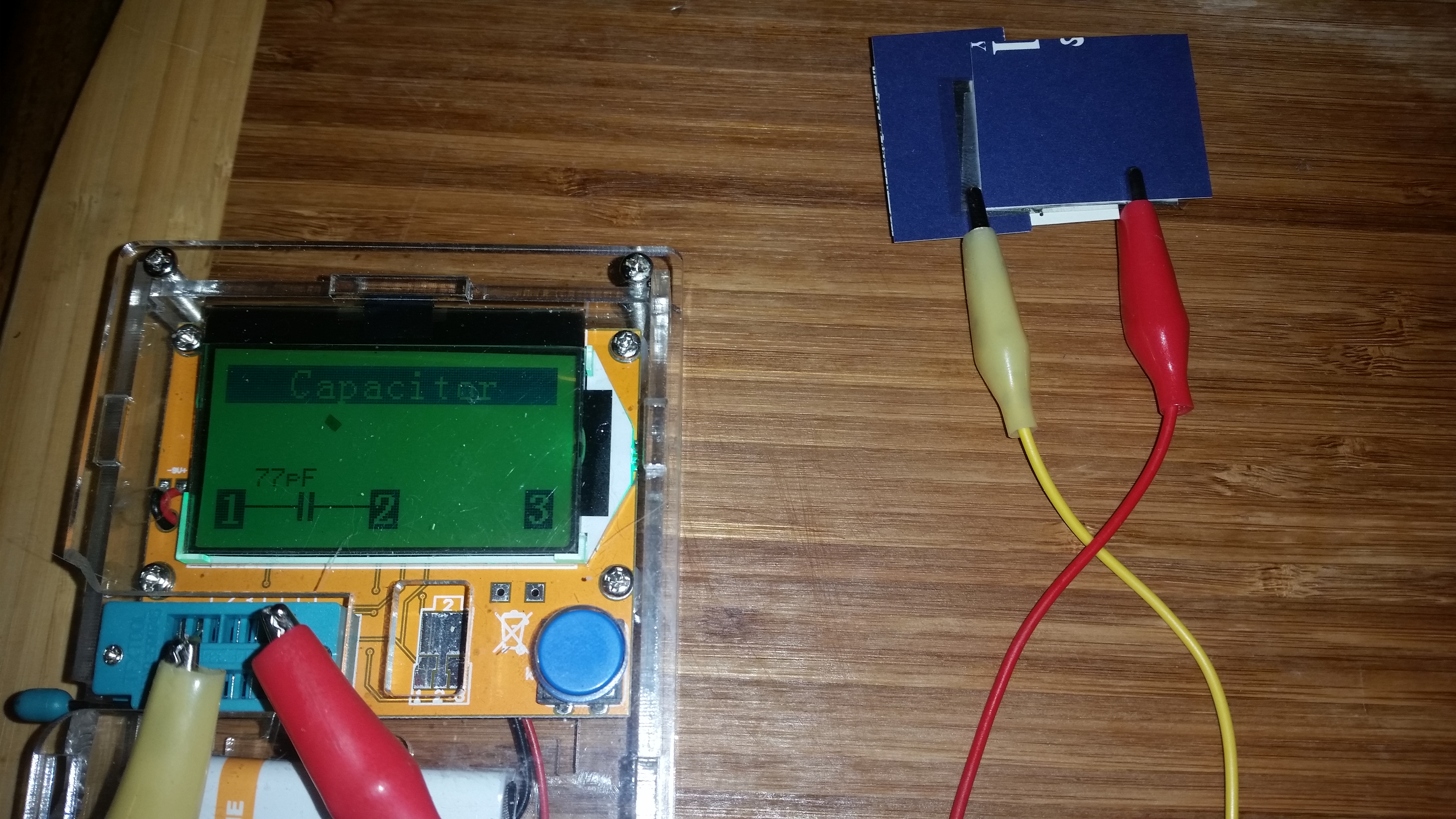
It works!
After printing a simple compression frame, the capacitor ended up at about 214pF. This is less than when I was holding the leads — but it’s more consistent and a lot more reliable this way, even with a very simple frame.

A working, 220pF-ish capacitor.
Strips of metal, interleaved with sheets of mica, might help it get up into the nF range. But that’s a project for another day.
