
One common task for an electronic device is to read the position of a rotary input. This could be to determine the position of part of a mechanical assembly, or simply to allow the user to select from various options using a scroll wheel.
Rotary encoders generally come in two varieties — absolute and relative. Absolute encoders, as you might expect, convey information about their absolute position. Even if the system has been powered off, these encoders will tell the system exactly where it is (plus or minus one position count.)
Quadrature encoders, on the other hand, do not remember any information about their position. They simply allow the microcontroller (or other circuit) to determine how far the encoder has turned while the microcontroller is monitoring it. This is perfect for jog dials used by the user, where absolute dial position doesn’t matter. Also, they’re easier to manufacture and work with — just two signal wires will do (plus ground and power.)
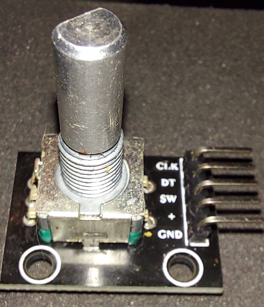
CLK and DT are the quadrature signals; SW is a normally-open SPST push switch contact.
Quadrature encoders are so named because they supply two phases of information, in quadrature. That is, these two phases transition 90 degrees apart in phase. One cycle of quadrature output (usually corresponding to one “click” of a dial) comprises four distinct phases. Turning it in one direction, the output might be
LL –> LH –> HH –> HL –> LL.
Turned the other way, this encoder would then output
LL –> HL –> HH –> LH –> LL.
Only one line changes state at a time (the criterion for a Gray code) — and by monitoring both lines, the direction of travel can be determined. (If the old state were HH, for example, the next state would have to be either LH or HL — one for clockwise and the other for counterclockwise. The state it changed into would tell you which direction it turned.)
As long as the microcontroller checks both lines faster than the maximum rate at which they can change, no position skip is possible. (Skipping may not be a huge issue on a jog wheel if it only happens once in a while — but skipping steps would make a positional encoder lose track of where it was, possibly causing a mechanical crash.)
Here is Arduino C code (tested on ESP32) to read two pins: ROTARYDAT and ROTARYCLK (defined elsewhere) to get the quadrature state of a rotary input, and update global integer variables called encHalfPhases and encTheta. (Using encHalfPhases directly resulted in the control being too sensitive to use reliably, so encTheta divides it by two.)
void IRAM_ATTR ISR() {

  //Interrupt handler for quadrature encoder on pins ROTARYDAT and ROTARYCLK.
  //Check the quadrature state, update theta, and GTFO...
  //CC:BY-NC-SA M. Eric Carr / Paleotechnologist.Net

  //Grab the new state (TODO: use raw GPIO reads to do this atomically and faster)
  uint8_t newState;
  newState=0x00;
  if(digitalRead(ROTARYDAT)){newState|=0x01;}
  if(digitalRead(ROTARYCLK)){newState|=0x02;}

  //Update enctheta based on pin state changes
  if((newState ^ encState) & 0x02){
    //Clock changed. Increment or decrement count based on if clk and data match
    if((newState & 0x01)^((newState & 0x02)>>1)){
      encHalfPhases++;}
    else{
      encHalfPhases--;}
      }

  //Update the encoder state
  encState=newState;

  //Update theta
  encTheta=(encHalfPhases>>1); //Divide by two. Shift may be faster than div??

  }
The code is written to be run as an interrupt service routine (ISR), so it should execute and return very quickly, with no loops or delays. Attach it to interrupt-on-change-capable pins as follows:
  attachInterrupt(ROTARYDAT, ISR_quadrature, CHANGE);
  attachInterrupt(ROTARYCLK, ISR_quadrature, CHANGE);
Through the magic of interrupts, when either pin changes state, the ISR_quadrature routine is called automatically, the saved state is updated, theta incremented, and control is handed back to the main program. All of this should take a few microseconds on most MCUs.
The IRAM_ATTR requests that the compiler place this routine in SRAM instead of Flash memory, for speed of execution (interrupt handlers should be very fast, because you want it to finish before another important interrupt event comes along.)
If implemented as an ISR tied to interrupt-on-change, this routine should work reliably to track quadrature changes. Use it to implement jog controls or to see how far your robot has traveled etc.
A subtle note: Although it may be tempting to use CLK and DT to clock directional data in to a D flip-flop, this setup can glitch if CLK is toggled without changing DT. The “Clock” and “Data” names are misnomers; thinking of them as Phase A and Phase B is safer.
