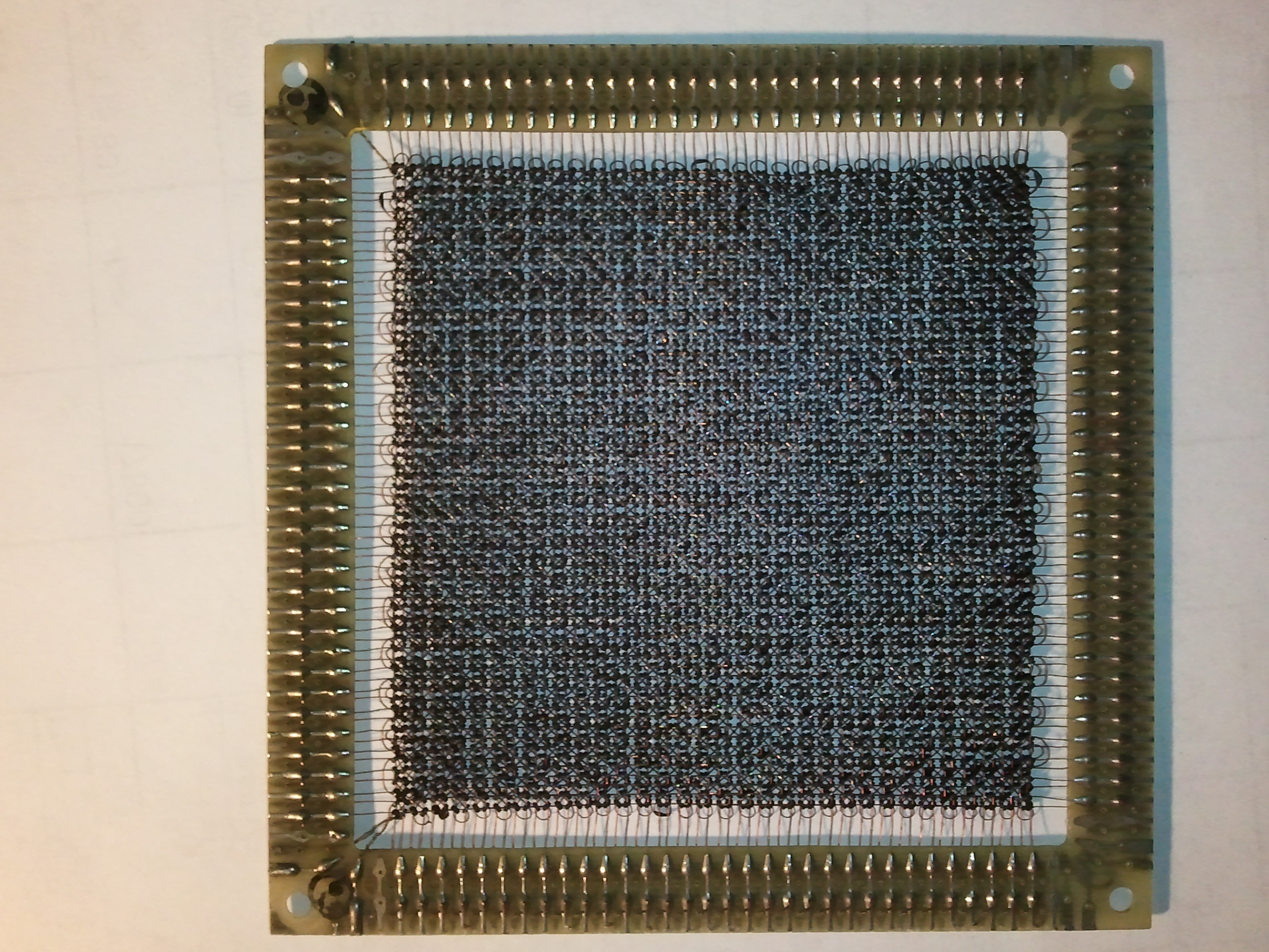
At its core (pun intended), Paleotechnology is really about rediscovering old technological methods and documenting them for future use. Just as archaeologists and paleontologists might piece together the history of a forgotten village based on buried pottery shards and the remnants of old buildings, paleotechnology concerns itself with rediscovering the way engineers made things work, years ago.
A good example of one technology that is becoming increasingly difficult to find information on is magnetic-core memory. Since, with core memory, there is a more-or-less fixed amount of construction effort required per byte of capacity (I.E. someone has to thread all those wires through all those cores), Moore’s Law doesn’t apply. For that reason, core memory (with its relatively constant cost-per-byte) was long ago surpassed by RAM and later technologies such as Flash memory.
Core memory stores bits in an array of ferrite cores — tiny rings made out of a ferromagnetic material which can be magnetized in one of two directions. Passing a large enough current through the core in one direction can record a “1”; passing a large enough current through the core in the opposite direction records a “0.”
The contents are read back via a destructive-read process: a “0” is written to the cell to be read. If the core was magnetized in the “1” direction, a small electrical pulse will appear on another wire passing through the core. If it was already a “0,” no pulse will appear (since writing a “0” didn’t change the magnetization of the core. What made core memory practical was an ingenious method of combining the currents from two different directions in order to select only one bit in an array.
The key observation is that a certain amount of current is needed to change the core’s magnetization. If only 60% of this current is used, the magnetic direction won’t change. Therefore, two wires can be passed through each core in an array: one for each row of bytes and one for each column. To write to a bit of memory, drive both the row and column lines in the correct direction, each with 60% of the critical current. Only the correct bit (at the intersection of those two wires) will be affected, since other bits will receive at most 60% of the critical current. (A third “sense” wire is threaded through many or all of the cores; the “sense pulse” that results when a “1” is converted back to a “0” is read out on this wire. This is the diagonally-threaded wire visible in the photo.)
This much theory is relatively easy to find online. The tricky part, I found, was in the details. How much current isthe right amount? Are we talking microamps, milliamps, or whole amps? I had found a plane of core memory (pictured above) on eBay a while ago and bought it with the intent of bringing it back online as a demonstration. What I didn’t want to do, though, was burn it out by using too much current.
Last quarter, I finally found the next few pieces of the puzzle. The professor teaching a course I was taking mentioned that the critical current was around 500mA. He also provided the title of a book with more details on the workings of core memory. I’m not sure why core memory is still being discussed in computer engineering courses in 2011, but I’m not complaining!
So, with this new information, I am beginning “Project Core II.” (The II referring to a second career for this particular plane of core memory.) Here’s the plan:
- Using an ohmmeter, test all 64 horizontal and 64 vertical wires, and the sense line for continuity. (DONE: everything seems fine!)
- Pass a wire through one “bit” of core memory (I found a bag of ferrite cores on eBay, too.)
- Pass increasing amounts of current pulses through it and see if I can sense pulses on a second wire.
- Once the pulses are observed, characterize what amount of current is required to make this happen.
- Try using a pair of wires to produce a combined current, and characterize what amount of current is required to drive the core using this method
- Try the above with several cores on a wire in one direction and a separate select line for each.
- Make a holder for the core memory plane, probably in the 3D printer. (I’d rather not solder directly to such a cool museum piece if I can help it.)
- Try sending pulses through the actual plane of core memory, starting out with low current values, and characterize what drive current is needed.
- Make a driver circuit (using a PIC and current-source circuitry) to store two or three bytes of information on a string of cores.
- Expand the driver circuit to cover all of the lines in the plane of core memory
- Design a nice interface for the thing and package it in acrylic as a demo piece.
- Run automated test patterns to check for various error syndromes.
- Perhaps design a simple PIC webserver, using the core as document-storage RAM!


Something which I think would be cool: Store a text on it (ASCII, uncompressed) and poll the memory at increasingly longer intervals, getting corrupted until it totally zeroes/corrupts.
Neat idea. I think core memory is nonvolatile, but that would be a nice visual way to test it. If/when I get it working, I’ll try that and post the results.