
The op amp (“operational amplifier“) has rightly been called the Swiss Army Knife of analog electronics. These integrated circuits are active devices with a deceptively simple description: high-input-impedance difference amplifiers with very high gain. Especially when connected in negative feedback, op amps can perform lots of useful functions on electronic signals.
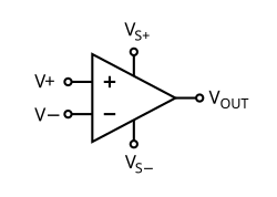
Vs+ and Vs- are typically connected to +15VDC and -15VDC supply rails.
V+ and V- are high-impedance inputs.
Vout is typically the difference in voltage between V+ and V-, multiplied by a large gain (of perhaps a hundred thousand times or more.)
When connected in negative feedback, two “golden rules of op amps” govern their basic behavior in electronic circuits:
- Little or no measurable current flows in or out of V+ and V- ; and
- Unless driven to saturation, the op amp will do what is needed to make its inputs equal.
That’s it. That’s what they do. The magic is in just how many ways this is useful:
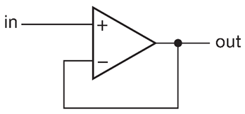
The voltage follower is the simplest closed-loop op amp circuit. It feeds the output back into the input. If the input voltage is even a little higher than the output, the output voltage rises. If the input voltage is lower, the output voltage drops. Either way, it reaches equilibrium when the output voltage equals the input voltage.
How is this useful? As an impedance converter. An op amp can take a signal with a very high impedance (that cannot source much current at all) and copy it as a stronger signal, capable of driving lower-impedance loads. And that’s just the beginning.
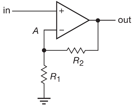
We can modify the simple voltage-follower so that the output voltage is sent through a voltage divider. Since the input node sees a fraction of the output voltage, the output voltage has to be (R1+R2)/R2 times the input voltage. So gain is 1+R1/R2.
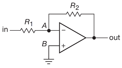
Similarly, we can make an inverting amplifier, with gain G=-R2/R1.
How does this work? Follow the rules: No current flows in or out of + and -, and A and B are at the same voltage. Since B is grounded, A is also at zero volts. So any input voltage applied will cause a current through R1. (Almost) no current flows into the op amp input, so this current has to also flow through R2. This means that the output voltage is inverted with respect to the input voltage: Vout is negative Vin, times R2/R1. Use equal resistors, and gain is G=-1.
We can make an inverting, summing amplifier as follows:
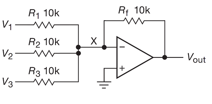
How does this one work? Point X is at ground due to how the amplifier works. Given that, the input impedance of each input is simply the value of its input resistor (10k for all inputs, in this case.) Therefore, a current of I= (V1/R1)+(V2/R2)+(V3/R3) flows past point X. For point X to be held at zero volts, the op amp must output a voltage of Vout=-I*Rf.
Since op amps are inherently difference amplifiers, they can be used to make difference amplifiers with modest gain, as well as their open-loop behavior:
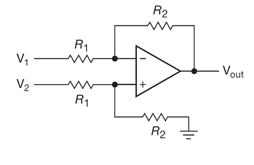
(If R2=R1, output voltage is equal to the difference in input voltages.)
These circuits are just the beginning — op amps can be used to make current sources (useful for LED strings), “ideal diode” circuits, integrators, differentiators, and lots more.
(I guess if they turned out to be useless, they’d be non-operational amplifiers!)
