Another trip up North, and another weird and wonderful device to investigate!
On a recent trip up to Maine, I came across a heavy device with a single knob that controlled a heading dial. (Dials marked 0-360 are almost always directional — and when they have 0, 90, 180, and 270 replaced with “N,” “E,” “S,” and “W,” it’s pretty much confirmed.)
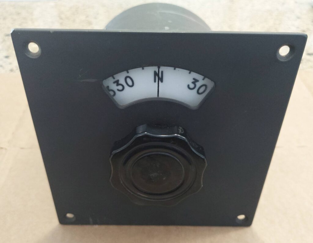
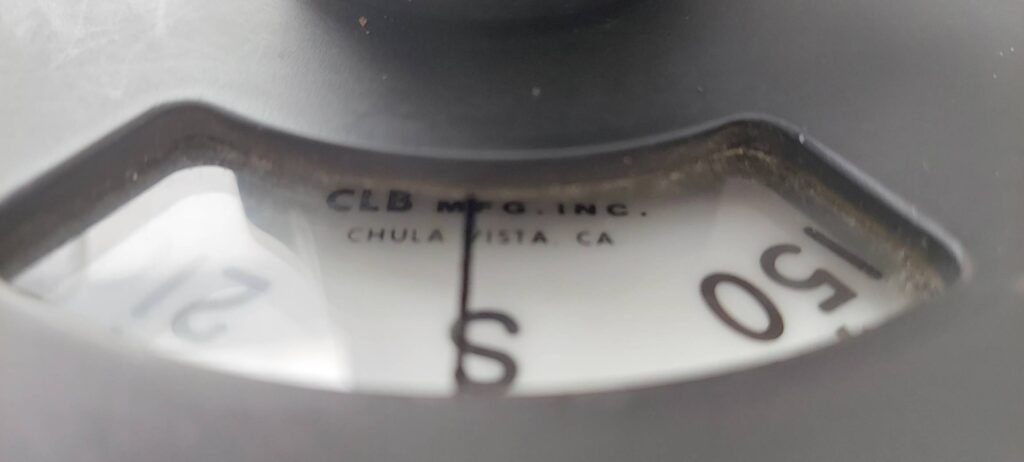
Turning the dial to S and looking in towards the shaft at what must have been an awkward viewing angle in its original mounting, I could see “CLB Mfg., Inc. Chula Vista, CA”
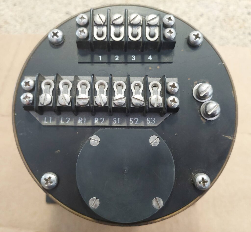
Looking at the back, I realized this had to be more complex than just a simple dial indicator. There were lots of connections — a set of what looked like three-phase windings, as well as “L1/L2” and “R1/R2” and whatever the heck terminals 1-4 are. Maybe L1/L2 and R1/R2 are Left and Right? For five bucks, how could I go wrong?
Whoa. Maybe it’s some kind of antenna rotator control?
Once I got it back to my folks’ place and could look at it more closely, I first tried to figure out what the electrical connectivity of the connections were. 1/2/3/4 were pretty clearly in some sort of Y configuration, with 4 as the common/center, and about 600 ohms from there to each of 1, 2, and 3. Symmetric coils, maybe? L1/L2 had some resistance between them, as did R1/R2. S1/S2/S3.
I decided to open it up to see if I could figure out anything.
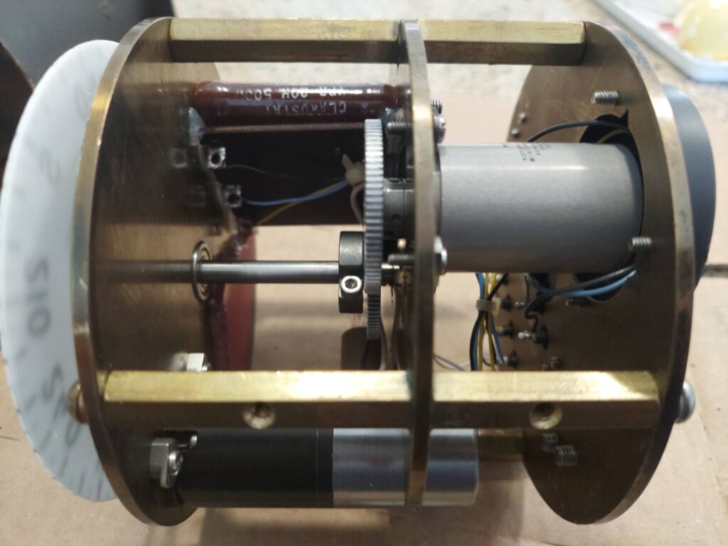
Wait — the transducer I was expecting, but not a motor!
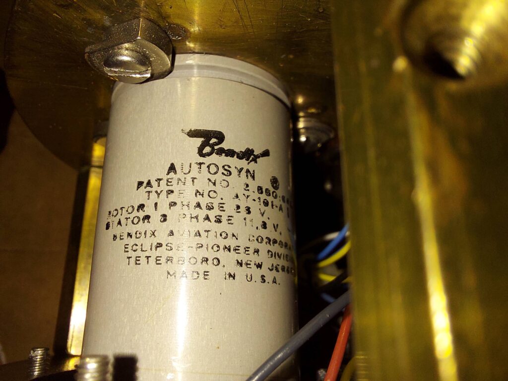
Seeing the inside just made it look weirder. There’s a Bendix “Autosyn” resolver geared 1:1 with the dial — but there’s also a 3-phase geared motor that can drive the shaft through a friction coupling. L1/L2 turn out to be Lamp connections; lighting the lamp would backlight the dial in red, for night operations. R1/R2 are the rotor connections to the Bendix resolver (which works with S1/S2/S3.) 1,2,3, and 4 are the Y-wound connections to the 3-phase motor, which seems to not have any positional feedback itself; the loop must be closed in external electronics, using the results from the Bendix.
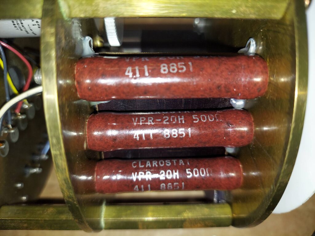
The motor winding connections are in phase with some beefy Clarostat 500-ohm resistors; these may be designed not only as series ballast resistors for the (completely unmarked) three-phase motor, but must also provide a nice, cozy warm environment for the mechanicals.
I’m still not sure exactly what it is — ChatGPT’s take on it is that it’s probably some kind of marine course selector/readout device, capable of both setting a course manually as well as having an autopilot device make course corrections via the 3-phase motor.
I guess the next step is a VFD to power up the 3-phase motor and see how it works…
