A Successful Failure

A2A simulations is building quite a reputation for themselves in the Flight Simulation community. Their attention to detail and focus on creating highly accurate models of important aircraft systems makes flying an A2A aircraft an immersive experience unlike anything else out there in the Flight Sim world. (Their B377 Stratocruiser, which I’ve written about before, is amazing!)

Recently, one of their developers was puzzled by a problem that had been reported when developing their P-40 fighter plane simulation. At high power, the engine would lose power — whereas actual P-40s would not, under the same conditions. There must be a fault in the simulation somewhere, right?

As it turned out, the simulation was working perfectly! In most simulated aircraft, the “engine” is really a straightforward set of equations relating fuel burn, manifold pressure, RPM, and torque/thrust. For simplicity, the internal workings of the engine are treated as a “black box.” On A2A aircraft with their “Accu-Sim” enhancements, though, engine systems are modeled much more accurately. Simulated fuel is pumped, a few cc at a time, into the carburetors, which mix it with air and feed the mixture to the simulated cylinders, which burn the fuel according to each cylinder’s timing, temperature, fuel/air mix, pressure, and other factors. If one of these parameters is incorrect, the cylinder will perform poorly — just as it would in a real engine. Cylinders can miss, for example, causing brief drops in RPM.

Troubleshooting the problem, A2A’s developer took the plane for a short test flight while keeping an eye on the engine instrumentation. He took off at reduced power, put the plane in a climb, then gradually added power. After the engine had been at full power for a while, he noticed the fuel pressure drop, after which the engine cut out.

It turned out that they had “installed” the wrong (simulated) fuel pump — which could not produce the needed fuel flow rate for the P-40’s (simulated) engine, starving it of fuel at high power settings. They’re working on correcting the problem (meaning, creating a higher-volume fuel pump simulation.)

You know you’re on the right track with your aircraft simulation, when diagnosing a failure comes up with a classic aircraft-engine problem, and the simulation gets the failure mode right!

 

Posted in Aviation, Digital, Flight Simulator, Nostalgia | Leave a comment

Chip packages

The same chip is often produced in several different packages. Here is an example: Microchip’s PIC16F1825 microcontroller, which is available in four different standard packages. The best package for your application depends on several factors. In many cases, it’s a tradeoff of size vs. ease of manufacturing.

One component; four different packages. (Click for larger.)

For hobbyists, DIP (Dual In-Line) form factor, also known as a “through-hole” component, is the easiest to work with. DIP parts (the top chip above is an example) can be used in circuit boards, placed in sockets, or used with solderless breadboards for quick prototyping of new circuits. They’re often quite a bit larger than other packages, though, so they’re not always the best choice for a manufactured product. Mounting DIP parts also requires holes to be drilled in the circuit board — an additional step which can add manufacturing expense.

The second chip from the top is the same 16F1825 microcontroller in SOIC (Small-Outline Integrated Circuit) packaging. SOIC chips are usually smaller than their DIP counterparts, and the leads are closer together. This allows them to take up less space on a circuit board, helping with device miniaturization. In addition, they (and the smaller types) are “surface-mount” (or SMT) components, meaning they do not require any holes to be drilled in the circuit board. They can be trickier to solder to than DIP parts, though, since the leads are closer together. You need a good soldering iron, thin solder, and good technique to solder these correctly.

The third chip from the top is the same 16F1825 microcontroller in TSSOP (Thin-Shrink Small Outline Package) form. It is similar to the SOIC form factor, but with much smaller lead-to-lead spacing. TSSOP parts are probably best handled with solder paste and a reflow oven.

Finally, the two chips at the bottom are in QFN (Quad Flat No-Leads) packaging. QFN-16 is the smallest standard size; for 14-pin parts like the 16F1825, this means that two of the pins are unused. (Two QFN chips are shown; the one on the right is upside-down to show the contacts on the bottom of the chip.) Since the contacts are on the bottom, solder paste and a reflow oven or hot-air rework station are required to work with QFN chips. These can save a lot of circuit board space (and therefore expense) in manufactured products, but can be very difficult to work with for hobbyists.

There are other popular chip packages available, notably “Quad Flat” packaging (QFP, LQFP, TQFP, etc); “Ball Grid Array” (BGA) packaging, and many others. These packages are mostly intended for use in manufacturing, though, although hobbyists continue to come up with novel ways to use them in homebrew devices.


Posted in Components, Electronics, Fundamentals | Leave a comment

Mystery Chip

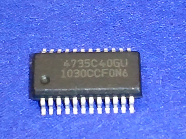
I recently placed an order with SparkFun. As usual, it got here quickly and they got the order right. They also included a bonus of sorts — a mystery IC. It’s quite small (SSOP-24?) You could park two or three of them on a dime and have space left over. Here’s a picture.

The Mystery Chip. (That's paper it's sitting on, not burlap!)

Looking up the markings online, I determined that it was a Silicon Labs SI4735 — a nearly-complete AM/FM stereo receiver chip! With the addition of a few passive components, it should be able to pick up broadcast radio stations (as well as shortwave and longwave!) Not bad for a bit of techno-debris that accidentally found its way into a shipping box.

I plan on making it into a working radio Real Soon Now™. When I do (and if I can actually solder to it), I’ll post it as a project on this site.

Posted in Analog, Components, Digital, Electronics, RF | Leave a comment

Components: Resistors

One of the most basic electronic components is the resistor. At first, these components don’t seem very useful; their function is to restrict (or resist) the flow of electrical current through a circuit. With today’s emphasis on efficiency, this seems pointless. However, various effects of resistors’ behavior make them important electronic components — and one of the easiest ones to understand. If you plan on building electronic circuits of more than the absolute minimum complexity, you will eventually need to understand and use resistors. Fortunately, this is easy.

Understanding resistors starts with an understanding of Ohm’s Law. (Voltage is equal to Current times Resistance. Follow the link above for a more in-depth explanation.)

Resistors come in many forms; perhaps the type most commonly used by hobbyists is the 1/4-watt, through-hole fixed-value resistor. These are axial components (meaning they have two connecting wires, initially 180 degrees apart), and are about 2mm in diameter at their thickest part (they would fit inside a typical drinking straw if not bent.) The example resistor shown below is of this type.

Typically, fixed-value through-hole resistors will have four color bands, which specify what the resistor’s nominal value and tolerance (margin of error) is. Here is a chart to help decode what the colors mean:

A well-known mnemonic (which I did not write) is: "Bad Boys Ravish Our Young Girls, But Violet Gives Willingly."


Here is an example of how these codes would be read on a garden-variety 1-kilohm (or “1k”) resistor. (Click on the image below for a higher-resolution version.) Reading the bands from the left, the brown band represents 1, and the black band represents 0. Putting these together gives “10” for the base value. (The first band is almost never black, except in the unusual case of a “zero-ohm” resistor: a single black band, otherwise known as a “wire.”) The third band is the multiplier band; red signifies multiplication by 100, making the total value 10 x 100 = 1,000 ohms — or “1k.” The 4th band is the tolerance band; gold signifies that the true resistance value of this component should be within 5% of the stated value (950 to 1,050 ohms).

A 1-kilohm resistor (10 + 0, times 100, is 1000 ohms). The wire is roughly as thick as a pencil lead. Click for larger.

Resistors are used for many tasks in electronics. Without going into too much detail, here is a sampling of some of their many uses:

  • Current-limiting: a 470-ohm or similar resistor is typically needed in series with an LED, in order to limit the amount of current flowing though the LED.
  • Voltage-divider use: Two or more resistors can be used to “divide” a voltage proportionately to the total resistance. For example, if a 2k and 3k resistor were placed in series between a 5V supply and ground, the voltage between the two would be 3V (if the 3k resistor was connected to ground) or 2V (if the 2k resistor was connected to ground).
  • As a “pull-up” or “pull-down” resistor: The voltage on an unconnected (or “floating”) wire is affected by nearby electrical fields, and tends to pick up a lot of noise. If such a wire is connected to the input of a digital circuit, the results will be unpredictable. A fairly high value resistor (1k is typical) is used to “pull up” the voltage to a logical high voltage (typically 5V or 3.3V) or “pull down” the voltage to ground. A switch can then safely be used to connect the input to the other value, without shorting anything out (the current through the resistor is small enough to be negligible.)
  • To measure current: A small, precise resistor (or strip of wire of known resistance) can be used to measure current passing through it. Since Voltage = Current times Resistance (V=IR), a current passing through a known resistance will produce a voltage differential directly proportional to that current. Passing, say, 3 amps through a 0.01-ohm shunt will produce a voltage of 30mV across the shunt. This can be measured by a voltmeter to infer the amount of current flowing through the shunt.
  • To discharge a capacitor: Some capacitors can hold a large amount of energy for a long time. When high-power equipment is turned off and the supply cord disconnected, it is safest if any capacitors can be automatically discharged. A “large” resistor (meaning one with a large resistance value, such as several kilohms or megohms) is permanently wired in parallel with the capacitor. When the power is turned off, this “bleeder” resistor safely discharges the capacitor.
Posted in Analog, Components, EET201, EET205, Electronics, Science | Tagged , , , , | 1 Comment