
The 555 timer IC (which I’ve covered before, but not in depth) is an interesting device. Recently, Jeri Ellsworth wondered on Facebook why the 555 wasn’t used in more designs. One thing led to another, and www.555contest.com was created. It has since really snowballed, and now Jeri, Forrest Mims, and Hans Camenzind (the inventor of the 555) are involved, along with many others. Good times to be an electronics geek, that’s for sure!
I’m a Digital Design geek by nature, so one of the first thoughts that occurred to me was to see if the 555 could be made to do Boolean logic. Looking at the schematic from the datasheet, it became apparent that it could, in fact, implement one (OK, two) of the six universal two-input gates. As it turned out, its specific native gate type is “A * ~B,” (“A AND NOT-B” or, if you like, “B AND NOT-A”) which is one of the two asymmetric universal gates (in other words, good luck finding *that* one as a 74xx chip. Or minimizing for it, for that matter!)

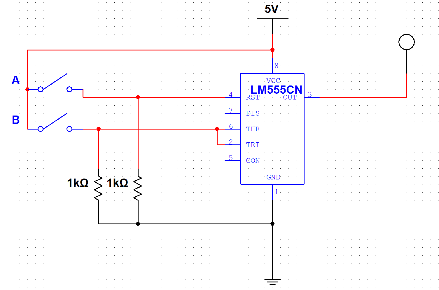
The native "A and NOT B" gate type for the 555
A test of the "A AND NOT-B" gate (click image for larger view)
“A*~B” gates are, however, universal: they can be combined to make any other type of logic gate. Tying A high, the gate becomes an inverter, which can then be used to make the basic gate into an AND or NOR gate, depending on which input is inverted.

An inverter made from the native A and NOT B gate

An AND gate, made from two 555s

A NOR gate made from two 555s
Adding a second 555-based inverter on the output creates a NAND or an OR gate, respectively.
This is, of course, an “off-label” use of the 555, so I tried various 555-based gates out in MultiSim. They worked well, so I physically built one of each, just to make sure they really would work that way. I haven’t done XOR and XNOR yet, but they can be made with combinations of the others (OR-and-NAND, and NOR-or-AND, respectively.) Here’s a video.
The circuit starts off (the two blue LEDs on the left) with a pair of 555s, each running in astable mode at a few Hertz each. The leftmost 555 runs at roughly — but not exactly — half the frequency of the second, providing interesting patterns as the two oscillators drift in and out of phase.
The third 555 (first green LED) is an inverter, with the “A” input () tied high, and the input of the faster oscillator tied to the “B” input.
The fourth 555 (second green LED) is a buffer, with the “B” input () tied low. It repeats the logic output of the inverter, and is included mostly because it was easy to do and for completeness.)
The fifth and sixth 555s form a NOR gate (red LED), with the 5th inverting the “A” input of the 6th, making a “NOT A AND NOT B” (NOR) gate.
The 7th and 8th 555s form an AND gate (yellow LED), with the 7th inverting the “B” input of the 8th.
555s 9 though 11 form a NAND gate (white LED; an AND gate with an inverted output).
555s 12 through 14 form an OR gate (purple LED; a NOR gate with an inverted output).

Yes, those really are 555s! (Click for larger view)
I’m currently working on a complete working computer made entirely from 555s (and a few diodes, at least for now, to reduce the part count a bit — although strictly speaking, these could be eliminated as well; flip-flops can be constructed from TTL gates. I have most of the design thought out, and hope to have the memory subsection (4 words of 6 bits, including addressing demultiplexer and I/O bus multiplexer) working in time for the 555 contest deadline. The rest of the computer is known to be possible, but unfortunately won’t be done in time for the contest; I’ll have to settle for submitting pieces and a sketch of how the whole thing would work. (Hey, that’s about as far as Babbage got!)

Pingback: Building a computer out of 555 chips | The Depot of Talk