Vector Boards (old-school prototyping)


An older alternative to breadboarding is vector board. Prototyping with vector board involves inserting specialized “vector springs” into a board with pre-drilled holes. A pin insertion tool is used to insert the springs as well as to open them up to insert wires and/or component leads.

Vector board, pins, and insertion tool. (Click for larger.)

The first step is to use the tool to insert the pins. These are not easily turned once inserted, so it’s important to align them the way you want (or allow extra lead length).

A vector pin in the insertion tool. (Click for larger.)

Once the pins are inserted, the tool is turned 90 degrees to press down on the spring and open the pin up so wires or leads can be inserted.

Using the insertion tool turned 90 degrees to compress the pin for component insertion. (Click for larger.)

The rest of the circuit is constructed this way. It can be tricky to get both ends of a component seated using only one vector tool, since only one pin can be easily opened at a time. (A fingernail or screwdriver could be used, in a pinch.)

A simple circuit, built using vector board. (Click for larger.)

Overall, I can see why vector boarding isn’t popular these days — it’s quite a bit more time-consuming to build circuits this way, compared to using solderless breadboards. The circuits, once constructed, seem to be nearly as robust as if wire-wrap had been used, and a bit more reliable than breadboarded circuits.
Posted in Electronics, Nostalgia | Leave a comment

Bah Humbuck

Recently, I stumbled across a basic $25 electric bass in Goodwill and bought it to see what it was like. I brought it with me to visit my folks; one thing led to another and they offered to get me a much nicer Ibanez as a graduation present. I’ve been enjoying studying bass-playing techniques, but as an electronics enthusiast, I find the construction details as interesting as the musical aspects of the instrument.

When you determine the frequency range of an electric bass, for instance, you find that it covers the 60Hz US household AC power frequency. (If 60Hz were a note, it would be almost exactly halfway between A#1 and B1. Incidentally, it would also be a very precisely-played note.) For an EE type — even a Digital specialist like me — that brings up an important question. How do you filter out the 60Hz influence, when that frequency is solidly in the range of frequencies you’re interested in preserving? You can’t really use standard filtering techniques like a notch filter — in order to cut the 60Hz by 20dB or so, while not appreciably chopping the two notes on either side of it, you’d need to have a cutoff curve of something like 240dB/octave, which would be difficult to say the least.

So, how do they do it? DSP? Use super-heavy shielding for the electronics and keep the (metal) strings away from 60Hz influences? As it turns out, there’s a simpler solution — humbucking.

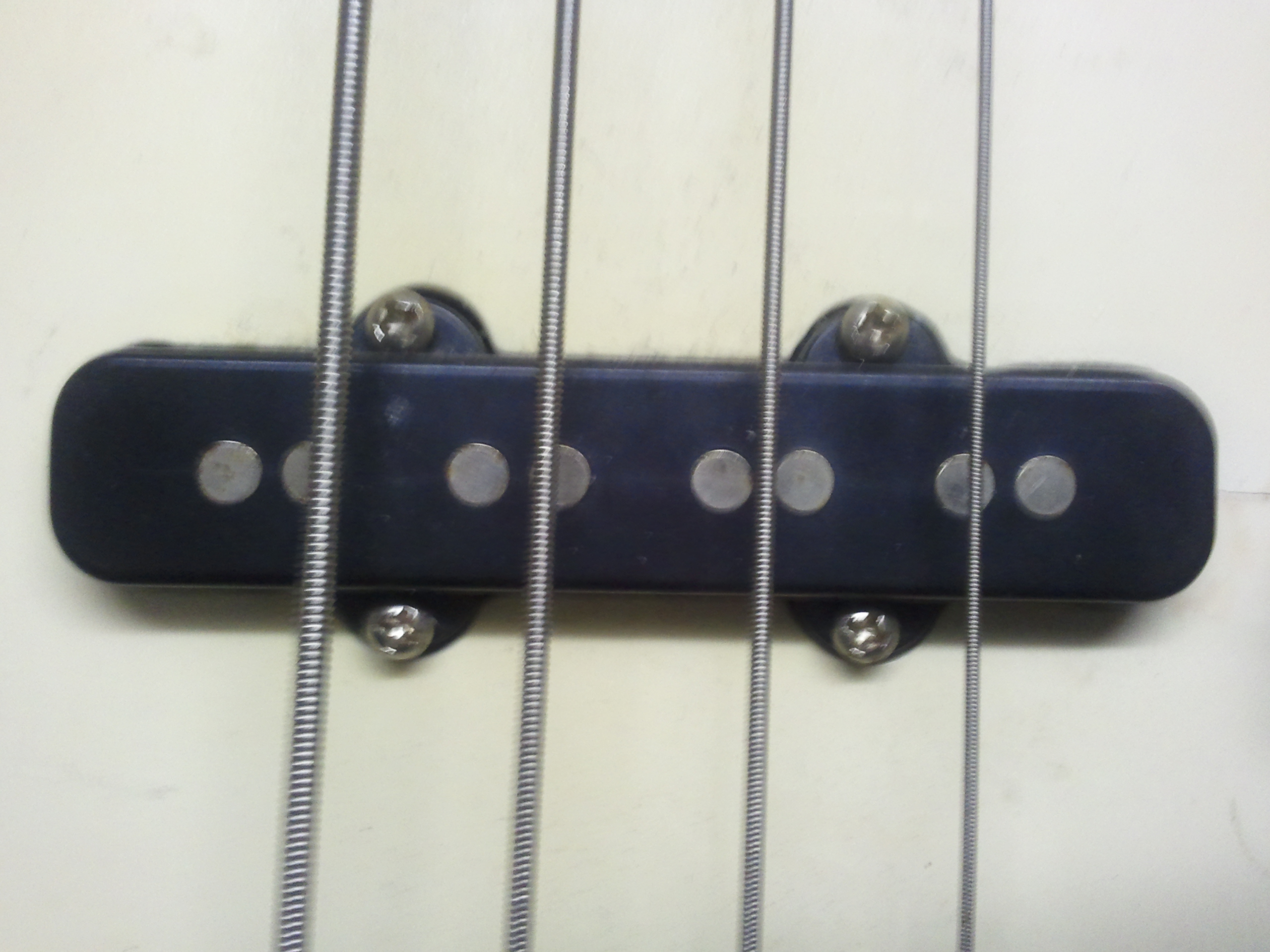
Humbucking relies on the use of two pickup coils per string. These are connected in series,  with one coil placed in the opposite direction from the other. This geometry causes any electric field crossing both coils to be more or less canceled out: 60Hz noise from nearby AC-powered equipment will induce an in-phase current in one coil and an out-of-phase component in the other. Since the two coils are in series, these two induced currents will (nearly) cancel, greatly reducing the amount of 60Hz noise picked up by the instrument.

Doubled (humbucker) pickups on an inexpensive bass guitar. (Click for larger.)

…Now if only there were a similarly elegant solution to help learn how to play the thing!


Posted in Analog, Audio, Electronics, Music, Toys | Leave a comment

MIT 6.002X pilot course

MIT’s beta-test of their online “MITX” program launches today, with the first day of class for their 6.002X “Circuits and Electronics” course. This is a free course, open to anyone, and MIT is offering a certificate of completion for anyone who finishes the course with good grades.

The syllabus is full of useful topics, from the basics of electrical theory (units of measure, Ohm’s Law, KVL/KCL) to more advanced topics like feedback, stability, transients, etc.

The price is certainly right and the content looks interesting and useful. I’d recommend anyone interested in learning more about the fundamentals of electronics sign up before the course gets too far along. (Although I’ve been working with electronics for several years now, I’ve signed up to see if there’s anything I’ve missed — which is quite probable considering that my background is mostly in Digital.)

The first homework is due March 16th, so now is a good time to get started!

Posted in Analog, Current Events, Digital, Electronics, Fundamentals, Internet | Leave a comment

The Periodic Table of 2-Input Logic Gates

For a two-input, one-output digital logic gate (assuming no state memory or feedback), there are a total of sixteen possible behaviors, since for each combination of inputs (00, 01, 10, and 11), the gate must output either a zero or a one. Combining these four behaviors allows description of the gate with four bits, meaning there are sixteen possibilities (0000 through 1111).

Not all of these “gate types” are interesting, however. For example, the “Type 0” gate (whose descriptor is 0000) always outputs a zero, no matter what the inputs are. Similarly, the “Type 15” gate (descriptor 1111) will always output a one.

Some interesting properties that some of the gates have are:

  • Symmetry: If you swap inputs A and B, will the gate act the same way?
  • Triviality: Is the “gate” so trivial that a simple wire will suffice?
  • Commonality: Is the gate a “standard” or commonly-used gate?
  • Inversion: Can the gate invert one or both inputs in at least some cases?
  • Two-input: Do both inputs affect the gate’s output?
  • Universality: Can several of this gate be used to emulate any other gate?

Here is a chart showing the properties of all of the possible behaviors a simple two-input-one-output digital logic gate could exhibit. Some of these are not true “gates”; others are, but lack universality. Interestingly, six of the gate types are universal — meaning that given a sufficient number of them, any other gate type could be created. An entire computer could be created using nothing but NOR gates, for instance.

A chart of all possible simple two-input logic gates. (Click for larger.)

Logic gates of various types can sometimes show up in unexpected places. The humble 555 timer IC, for example, turns out to be capable of functioning as a Type 2 (or Type 4) gate. Since these are universal, a computer using only 555s as active logic is possible!


Posted in Digital, EET205, Electronics, Fundamentals, Math | Leave a comment
